Badger Meter GMD Gage User Manual
Location, Installation, Operation
LOCATION
A. The GMD can be line, bracket or panel mounted.
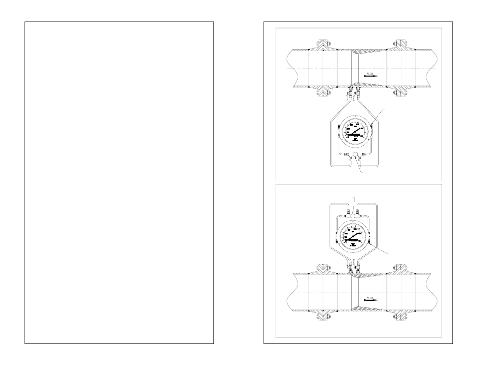
B. For liquid applications the GMD should be installed below the
primary element in a level position (see diagram 1).
If recommended mounting is not possible, care must be taken to
ensure that the gage is vented periodically.
C. For air/gas applications the GMD should be installed above the
primary element in a level position (see diagram 2).
Installation
A. The connecting tubing between the primary element and the
gage should be as short as possible and should slope a mini-
mum of 1 inch per foot.
B. Secure and support tubing to prevent sagging and or vibration.
C. Care must be taken to ensure that the head heights are even.
D. A Bleed line should be run from the GMD vent valves to a pan
or drain.
Operation
**Preso strongly recommends the use of a single valve bypass or a
3-valve manifold with the GMD gage**
A. Identify Hi and Lo pressure inlets on the GMD.
B. Ensure bypass valve is OPEN! If no bypass, extreme caution
must be used when opening Hi and Lo valves on the primary
element. The valves must be opened simultaneously to prevent
over pressurization and possible damage to the gage.
C. Connect GMD to corresponding Hi and Lo pressure taps of the
primary element (via 3-valve manifold, if being used).
D. Open Hi and Lo instrument valves on the primary element.
E. Alternately open the Hi and Lo vent valves to purge the lines.
F.
When venting is complete, close the bypass valve to begin
taking readings.
Maintenance
Normal operation requires no maintenance. In case of dirt or scale
build up flush meter with clean water or a compatible solvent.
>>> Contact your local representative if you have any <<<
>>> questions regarding PRESO products <<<
RECOMMENDED LIQUID INSTALLATION:
H
L
(DIAGRAM 1)
VENT VALVES
BYPASS VALVE
(DIAGRAM 2)
BYPASS VALVE
RECOMMENDED GAS INSTALLATION:
VENT VALVES
H
L