Installation instructions, double support – Badger Meter Model BHR User Manual
Page 6
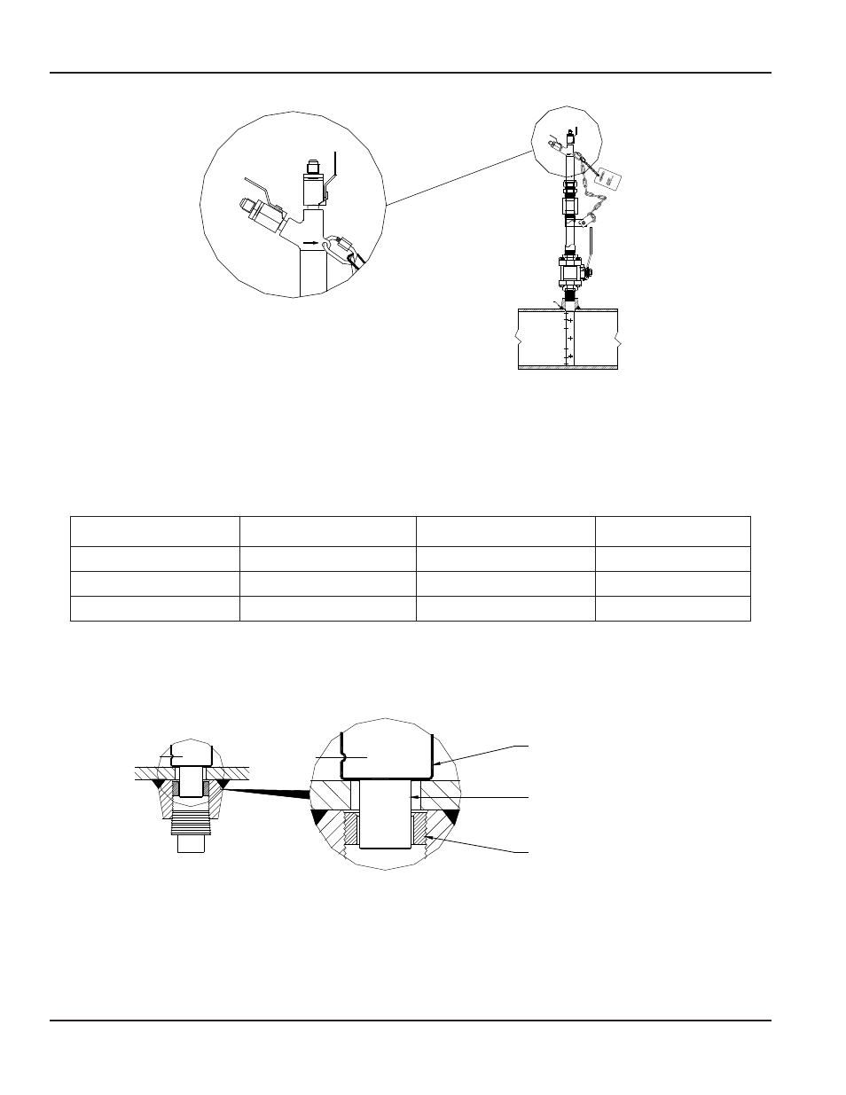
Field Weld
H
L
H
L
Figure 4: Sensor alignment
INSTALLATION INSTRUCTIONS, DOUBLE SUPPORT
1 . Follow steps 1 through 10 in
“Installation Instructions, Single Support” on page 5
. At 180° from and on the same plane
as the previously drilled hole, grind the surface of the pipe to provide a clean area for welding . Drill a hole and deburr,
especially on the inside of the pipe . The hole used for the double support should be sized according to
.
Pipe Size
Model / Sensor
Weld Connector
Drill Bit
2"…5"
BHR (7/16")
1/2"
3/8"
6"…12"
BHRL (7/8")
1/2"
1/2"
14"…24"
BHR (1-1/4")
1"
7/8"
Table 3: Double support drill bit size
2 . Weld the double support thread-o-let making sure that it is centered with the drilled hole (1/16" weld gap recommended) .
3 . Install the BHR Ellipse sensor through the two holes . Make sure that the double support pin passes through the guide ring .
See
Ellipse Sensor
Double Support Pin
Guide Ring
Figure 5: Double support pin
4 . Align the arrow located on the sensor head in the direction of flow as in step 11,
“Installation Instructions, Single Support”
5 . Check that the BHR Ellipse is in the correct orientation and spans the inside of the pipe . Tighten the compression nut
manually, then use a wrench to tighten it an additional 1-1/4 turns .
6 . Install the plug into the end of the double support thread-o-let . Tighten the plug to prevent leakage .
Ellipse® Pitot Tube Meter, BHR Annular Wet Tap with Safety Chain Meter
Page 6
April 2014