Installation instructions, single support, Flow – Badger Meter Model BAR User Manual
Page 5
User Manual
Page 5
April 2014
INSTALLATION INSTRUCTIONS, SINGLE SUPPORT
1 . Choose the proper location to install the BAR Ellipse using AGA/ASME standards (or equivalent) . See
2 . Grind the surface of the pipe where the BAR Ellipse is to be inserted to provide a clean area for welding .
3 . Weld the supplied thread-o-let to the pipe using standard codes for your application (1/16 in . weld gap recommended) .
Take care to protect the threads during the welding process .
4 . Drill a hole through the pipe wall according to
.
Pipe Size
Model/Sensor
Weld Connector
Drill Bit
2…5 in .
BAR (1/2 in .)
1/2 in .
5/8 in .
6…12 in .
BAR (7/8 in .)
1 in .
1-1/8 in .
14…24 in .
BAR (1-1/4 in .)
1-1/4 in .
1-3/8 in .
Table 2: Single support drill bit size
5 . De-burr the hole just drilled, especially on the inside of the pipe .
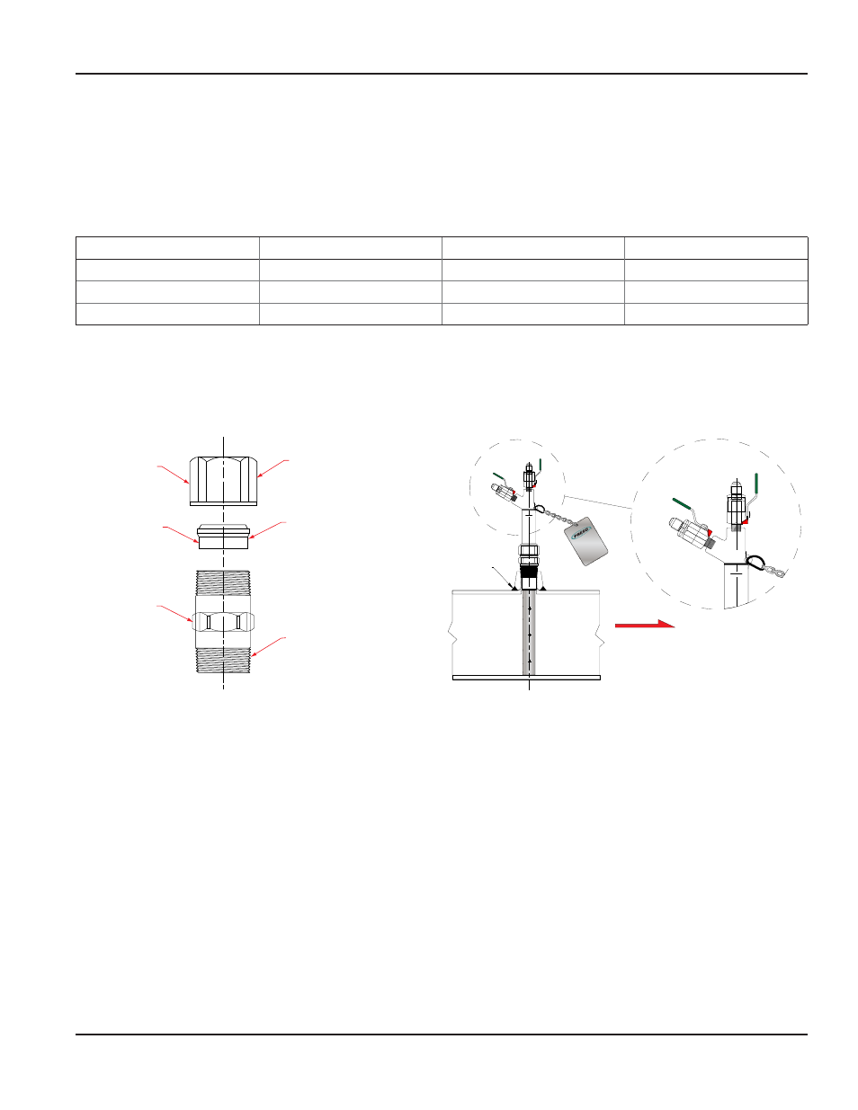
6 . Assemble the supplied compression fitting as shown in
. Thread the assembled compression fitting into the
thread-o-let manually . With a wrench, tighten the body of the fitting another 1-1/4 turns, being careful not to tighten the
compression nut .
Nut
Insert
Body
Thread nut loosely
onto body of the
compression fitting
Install insert
as shown
Install threaded
portion into weld
fitting on pipe
FLO
W M
ETE
RS
DEB
ITM
ETE
RS
MED
IDO
R D
E F
LUJ
O
FLOW
Field
Weld
H
L
H
L
Figure 4: Single support installation
7 . Install the instrument valves (optional) at the BAR Ellipse head connections . Make sure that the valves are fully closed to
prevent them from leaking during start-up .
8 . Insert the BAR Ellipse through the compression fitting . Carefully push the sensor into the pipe until it reaches the
opposite wall .
9 . While holding the BAR Ellipse in its fully inserted position, align the arrow on the sensor head with the direction of flow .
See
10 . Manually tighten the compression nut in order to prevent leakage, then use a wrench to tighten the compression nut
another 1-1/4 turns .