Installation instructions, single support – Badger Meter AHS - Hot Tap, Steam (2 to 24")" User Manual
Page 5
INSTALLATION INSTRUCTIONS, SINGLE SUPPORT
1 . Choose the proper location to install the AHS Ellipse using AGA/ASME standards (or equivalent) . See
“Preso Ellipse Location
Instructions” on page 7
.
2 . Grind the surface of the pipe where the AHS Ellipse is to be inserted to provide a clean area for welding .
3 . Weld the supplied weld-o-let to the pipe using standard codes for your application (1/16" weld gap recommended) . Take
care to protect the threads during the welding process .
4 . Thread the close nipple into the weld connector . Install the supplied three-piece isolating ball valve .
5 . Mount the high pressure drilling machine onto the ball valve . Open the ball valve . Drill a hole through the pipe wall
according to
.
OTEE:
N
There is no need for a drilling machine if it is not a hot tap installation or if the system is not pressurized .
Model / Sensor
Weld Connector
Drill Bit
AHS (7/8")
1-1/4"
1-1/8"
AHS1 (1-1/4")
1-1/2"
1-3/8"
Table 2: Single support drill bit size
6 . Withdraw the drill bit through the isolating valve, close the valve and dismantle the drilling machine . Make sure there is no
leakage at the valve and close nipple connections . The valve is to remain completely closed until step 9 .
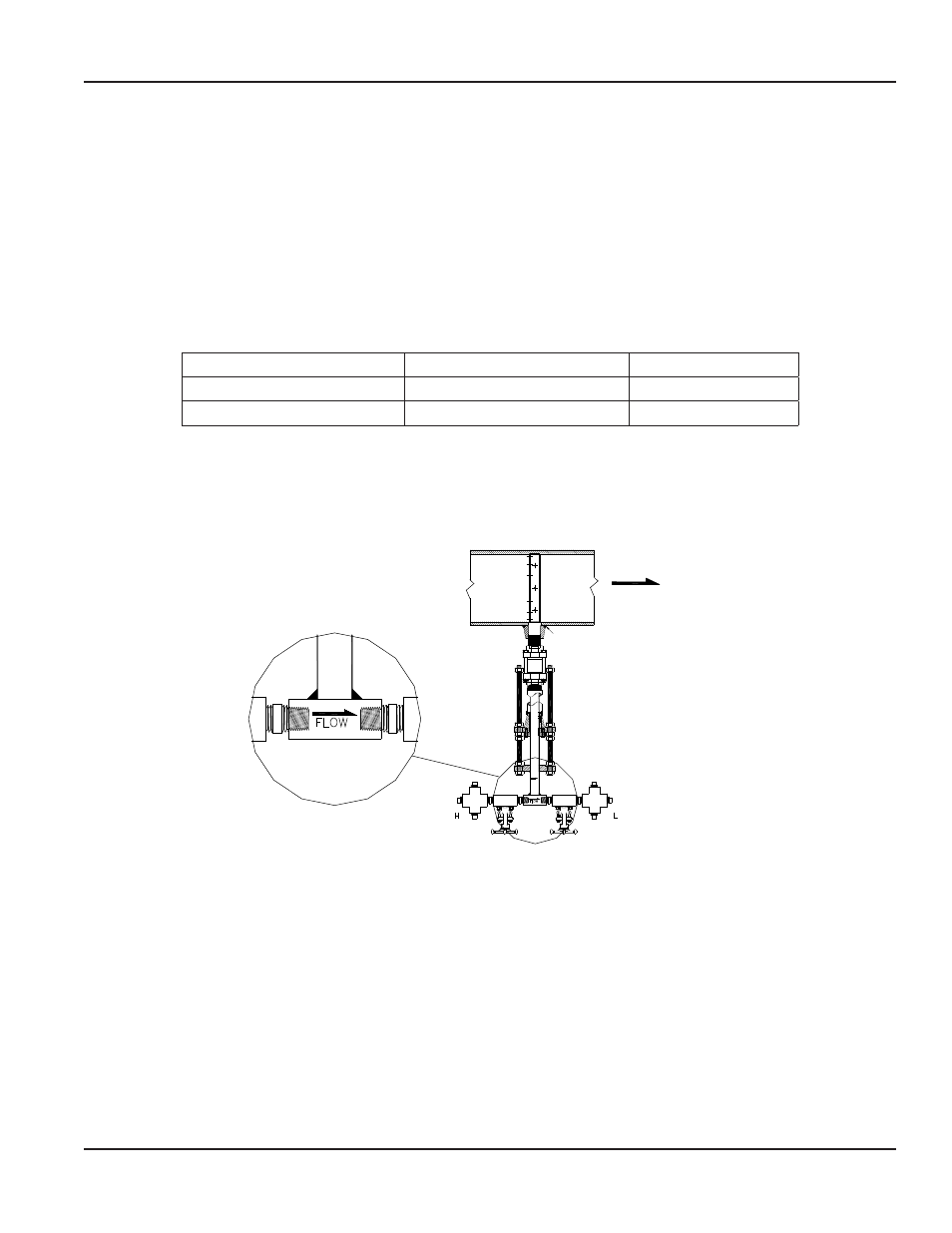
7 . Install the cage nipple, cage nipple assembly and packing gland with the threaded rods assembly by threading it into the
isolating valve . Align the arrow on the sensor head with the direction of flow . See Figure 4 .
Field Weld
FLOW
Figure 4: Sensor alignment
8 . Install the instrument valves at the AHS Ellipse head connections . Make sure the valves are fully closed to prevent them
from leaking upon startup . Install the cross tees .
9 . Open the isolating ball valve . Insert the AHS Ellipse sensor into the pipe until it reaches the opposite pipe wall . This should
be done by turning the threaded insertion rods clockwise using a wrench .
10 . Connect the instrument lines to the sensor head valves . In turn, connect these lines to a gage or transmitter .
11 . Verify that the instrument valves are FULLY CLOSED . Remove the1/2" plugs from the top and side ports of the two (2)
forged cross tees .
12 . Slowly pour water into the top ports of each forged cross tee until the system is full . Water will flow out of the side ports of
both crosses .
13 . Reinstall the 1/2" plugs into the top and side ports . Ensure that they are secure . Then fully open the two (2) gate valves .
14 . Allow condensation levels to stabilize 1/2 hour before taking instrument reading .
User Manual
Page 5
April 2014