Installation instructions, double support – Badger Meter AHR - Wet Tap, Low Pressure (2 to 36")" User Manual
Page 5
THE ELLIPSE AHR MUST BE MANUALLY HELD IN ITS FULLY INSERTED POSITION UNTIL THE COMPRESSION NUT HAS
BEEN COMPLETELY TIGHTENED IN STEP 11 AND THE SAFETY CHAIN HAS BEEN PROPERLY ATTACHED.
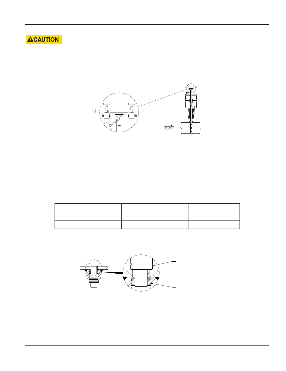
11 . While holding the Ellipse AHR in its fully inserted position, align the arrow on the sensor head with the flow direction .
Figure 3: Sensor alignment
12 . Completely tighten the packing gland to prevent leakage .
13 . Connect the instrument lines to the sensor head valves, then connect the lines to a gage or transmitter .
INSTALLATION INSTRUCTIONS, DOUBLE SUPPORT
OTEE:
N
For non-hot tap installations only .
1 . Follow steps 1 through 10 under
“Installation Instructions, Single Support” on page 4
. Size the hole used for the double
support according to the following table .
Model / Sensor
Weld Connector
Drill Bit
AHR (7/8")
1/2"
1/2"
AHR1 (1-1/4")
1"
7/8"
2 . Weld the double support weld-o-let making sure that it is centered with the drilled hole .
3 . Install the Ellipse AHR sensor through the two holes . Make sure that the double support pin passes through the guide ring .
See
Ellipse Sensor
Double Support Pin
Guide Ring
Figure 4: Double support pin
4 . Align the arrow on the sensor head with the direction of flow as in step 11,
“Installation Instructions, Single Support” on
5 . Check that the AHR Ellipse is in the correct orientation and spans the inside of the pipe . Tighten the compression nut
manually . Using a wrench, tighten the compression nut an additional 1-1/4 turns .
6 . Install the plug into the end of the double support weld-o-let . Tighten the plug to prevent leakage .
User Manual
Page 5
April 2014