Installation instructions, double support – Badger Meter AHL - Hot Tap, High Pressure (2 to 30")" User Manual
Page 5
User Manual
Page 5
April 2014
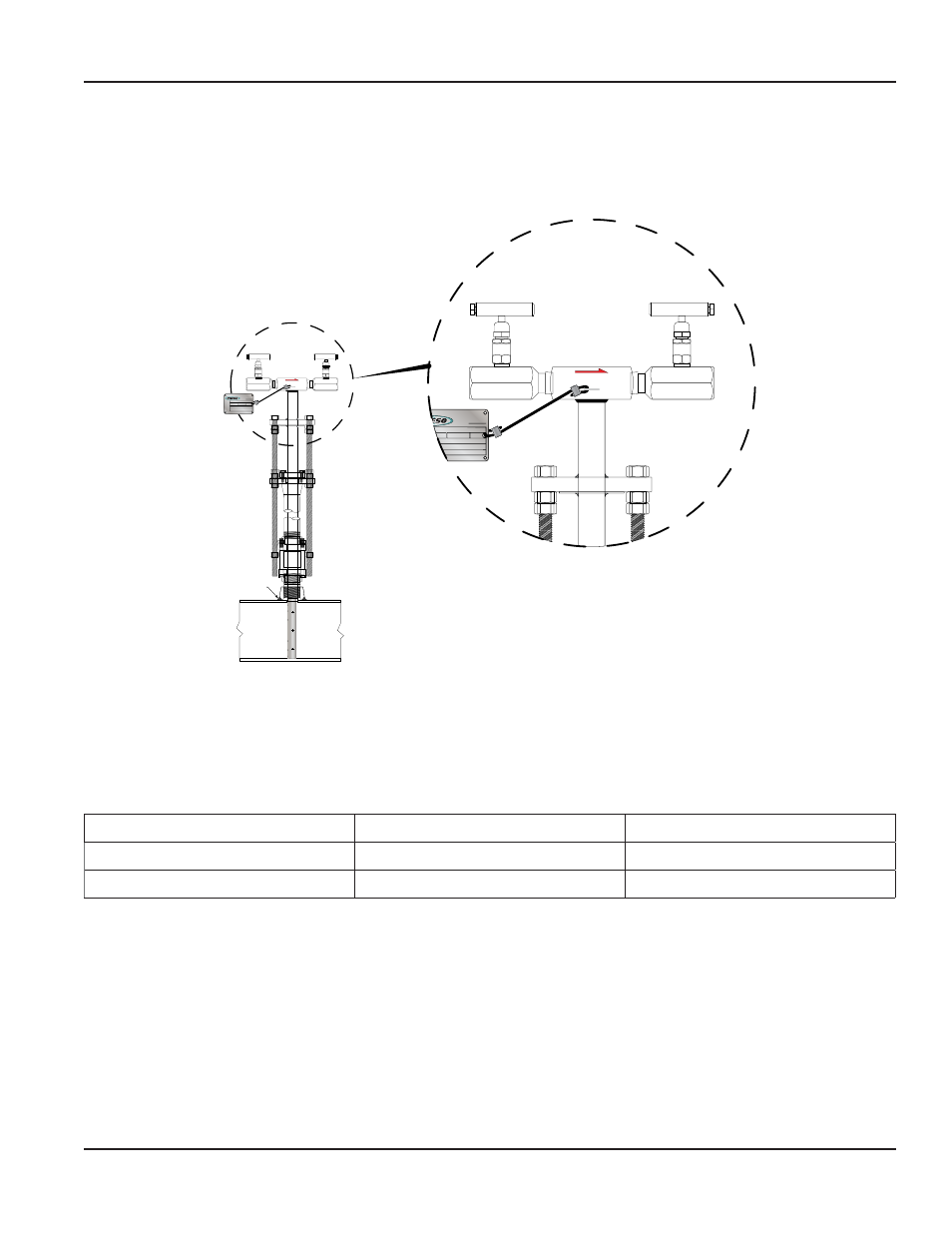
8 . Install the instrument valves (optional) at the pressure connections on the AHL Annular High Pressure Hot Tap Meter
sensor head . Make sure the valves are fully closed before proceeding .
9 . Open the isolating ball valve . Insert the AHL Annular High Pressure Hot Tap Meter sensor into the pipe . Use a wrench to
turn the threaded insertion rods clockwise until the sensor reaches the opposite pipe wall .
10 . Connect the instrument lines to the sensor head valves, then to a gage or transmitter .
SCH/WALL
FLOW METERS
W/O
H
L
FLOW
Field Weld
H
L
SCH/WALL
MOD/β
DIA/ID
CAP
DP
TAG
FLOW METERS
W/O
FLOW
Figure 3: Sensor alignment
INSTALLATION INSTRUCTIONS, DOUBLE SUPPORT
1 . Follow steps 1 through 6 in
“Installation Instructions, Single Support” on page 4
. At 180° from and on the same plane
as the previously drilled hole, grind the surface of the pipe to provide a clean area for welding . Drill a hole and de-burr,
especially on the inside of the pipe . The hole used for the double support should be sized according to
Model/Sensor
Weld Connector
Drill Bit
AHL (7/8 in .)
1/8 in .
3/8 in .
AHL (1-1/4 in .)
1 in .
7/8 in .
Table 3: Double support drill bit size
2 . Weld the double support thread-o-let, making sure that it is centered with the drilled hole (1/16 in . weld
gap recommended) .
3 . Install the AHL Annular High Pressure Hot Tap Meter sensor through the two holes . Make sure that the double support pin
passes through the guide ring . See
.