Installation instructions, single support, Flow – Badger Meter ASF - Steam (2 to 48")" User Manual
Page 5
INSTALLATION INSTRUCTIONS, SINGLE SUPPORT
1 . Choose the proper location to install the ASF Ellipse using AGA/ASME standards (or equivalent) . See
2 . Grind the surface of the pipe where the ASF Ellipse is to be inserted to provide a clean area for welding .
3 . Drill a hole through the pipe wall according to
.
Model / Sensor
Weld Connector
Drill Bit
ASF (7/8")
1"
1-1/8"
ASF1 (1-1/4")
1-1/4"
1-3/8"
ASF2 (2-1/4")
3"
2-3/4"
Table 2: Single support drill bit size
4 . Deburr the hole just drilled, especially on the inside of the pipe .
5 . Weld the mating flange assembly to the pipe . Align the holes . Allow 1/16" weld gap between the mounting flange and
the pipe .
6 . Install the gasket and place the ASF Ellipse sensor into the pipe .
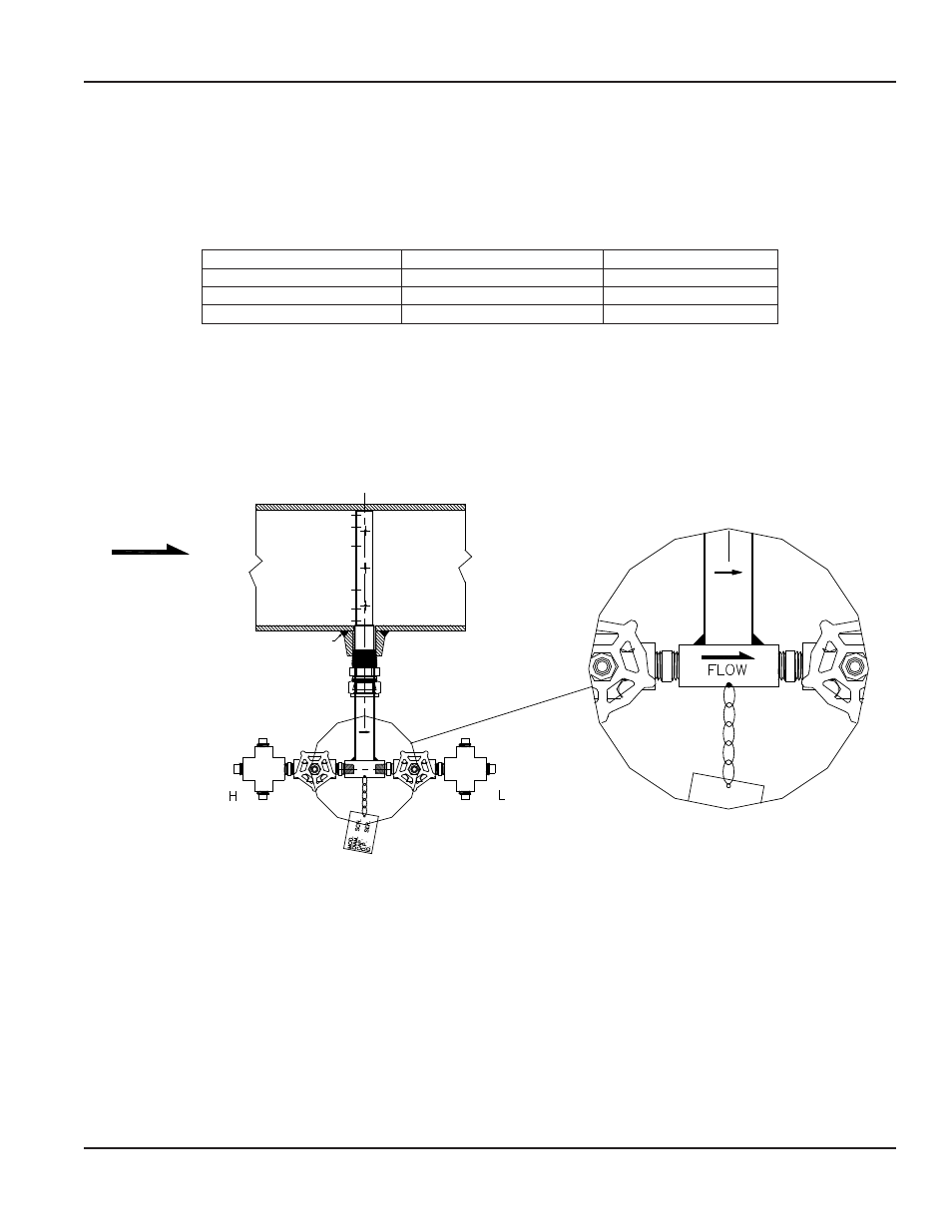
7 . While holding the ASF Ellipse in its fully inserted position, align the arrow on the sensor head with the direction of flow .
See
FLOW
Field Weld
Figure 4: Sensor alignment
8 . Tighten all of the bolts on the flange and assemble all the parts that make the instrument head .
9 . Connect the 1/2" tubing to the connections on the forged cross components . Connect these lines to a three-valve
manifold transmitter .
10 . Verify that the instrument valves are FULLY CLOSED . Remove the 1/2" plugs from the top and side ports of the two forged
cross tees .
11 . Slowly pour water into the top ports of each forged cross tee until the system is full . Water will flow out of the side ports of
both crosses .
12 . Reinstall the 1/2" plugs into the top and side ports . Ensure that they are secure . Fully open the two gate valves .
13 . Allow condensation levels to stabilize for 30 minutes before taking an instrument reading .
User Manual
Page 5
April 2014