Ac or dc power supply, Red black shield (if applicable) series 200 or sdi, Industrial – Badger Meter 330 Series Relay Transmitter User Manual
Page 3: Remote reset, Relay
3
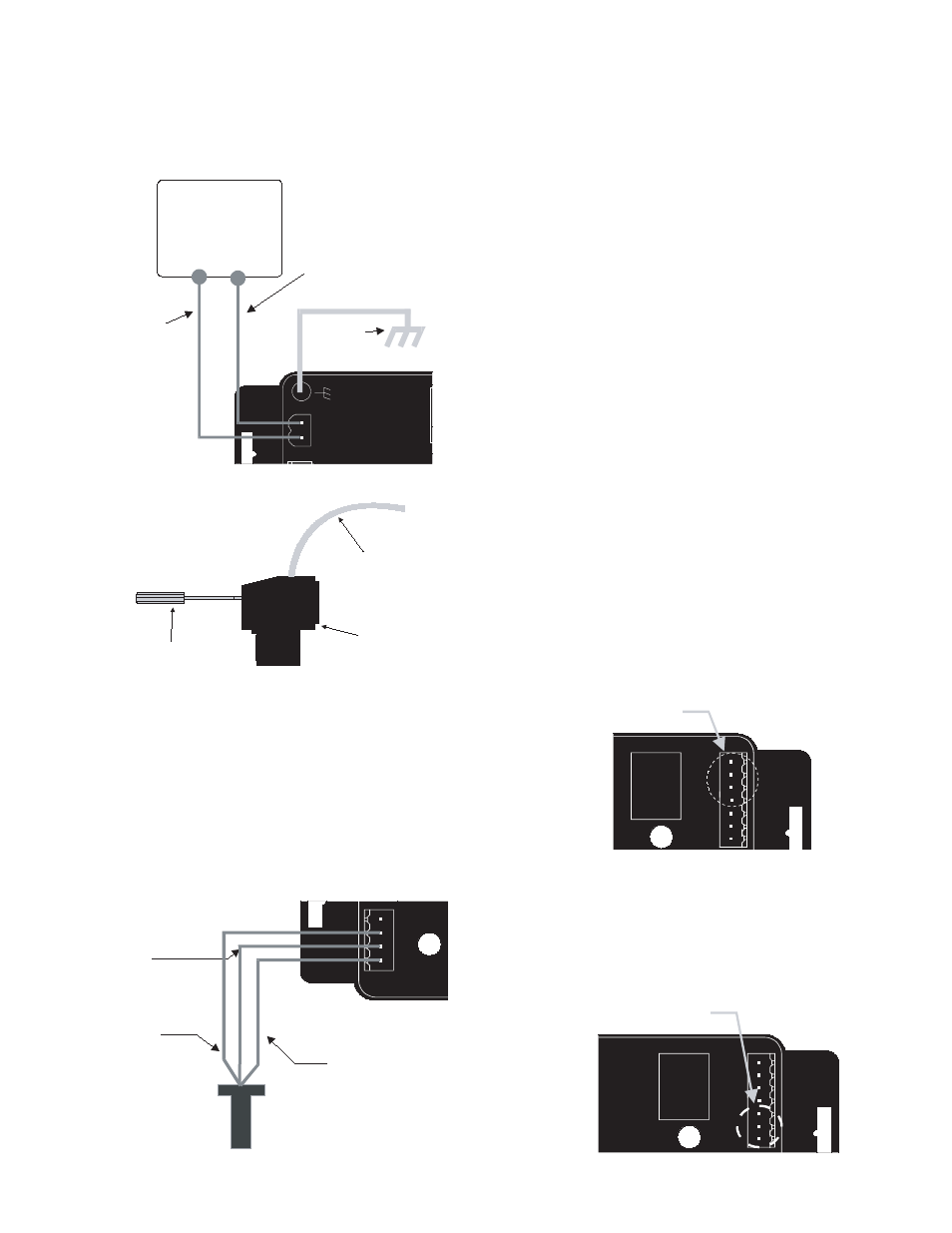
Sample Power Supply Wiring Diagram
®
Industrial
Power Out
(+)
(-)
Shield
AC Load/DC +
AC Common/DC -
DIC Comm.
Port
Output
Input
®
Model: 330
SN# 0000000
N.O.
ComA
N.C.
ComB
Hi
GND
Low
DC +
or
AC Load
DC -
or
AC Common
Earth
Ground
AC or DC
Power Supply
Side View - typical Series 300
Removable Connector Wiring
3/32” Flathead
Screwdriver
Series 300
Connector
Wire
Note:
Included with every Series 330 is a Series 330IK kit
containing a screw, lock washer and ground lead to
connect the Series 330 to earth ground. This will help
prevent electrical interference from affecting the Series
330’s normal operation.
Sensor Wiring
All flow sensor types connect to the four terminal header
shown in the “sample sensor wiring diagram.”
If sensor is a Badger
®
Series 200 then:
1) Connect the Red Wire of the sensor to Sensor signal
(+) on the Badger Series 330.
2) Connect the Black wire of the sensor to Sensor signal
(-) on the Badger Series 330.
3) Connect the Bare wire (if applicable) of the sensor to
the Shield terminal on the Series 330.
If sensor is a Badger Series 4000 then:
1) Connect the red wire of the Series 4000 to Power on
the Series 330.
2) Connect the black wire of the Series 4000 to the
Sensor (-) on the Series 330.
3) Connect the clear wire of the Series 4000 to the
Sensor (+) on the Series 330.
4) Connect the bare wire of the Series 4000 to the Shield
on the Series 330.
If sensor is a SDI Series with standard frequency (pulse)
output then:
1) Connect terminal 3 (sensor signal) of the SDI to
Sensor (+) on the Badger Series 330.
2) Connect terminal 2 (sensor common) of the SDI to
Sensor (-) on the Series 330.
3) Connect the terminal 1 (shield) of the SDI to the Shield
on the Series 330.
If sensor is a Non Badger Meter Flow Sensor:
The sensor input power terminal supplies nominal 9.1VDC
excitation voltage for 3 wire sensors. Connect sensor signal
+ and sensor signal - wires to transmitter terminals.
Relay Output Wiring
The Badger Series 330 is supplied with a removable DPST
relay with normally open and normally closed contacts. To
wire to the normally closed contacts connect to the terminals
“NC1” and “NC2”. To wire to the normally open contacts
connect to the terminals “NO1” and “NO2”. Note: this relay
may be used as a Form C relay. Use a jumper to connect
one terminal from each set together as the common
terminal.
Sample Sensor Wiring Diagram
®
Industrial
Power
(+)
(-)
Shield
AC Load/DC +
AC Common/DC -
DIC Comm.
Port
Output
Input
®
Model: 330
SN# 0000000
N.O.
ComA
N.C.
ComB
Hi
GND
Low
Red
Black
Shield
(if applicable)
Series 200
or
SDI
Remote Reset Switch Wiring (if applicable)
The “Hi”, “Com”, and “Lo” terminals on the Badger Series
330 are used for a remote reset. If the remote reset device
provides a momentary dry contact closure - then connect
to the “Lo” and “Com” terminals. If the remote reset device
provides a momentary voltage (up to the supply voltage to
the Series 330) - then connect to the “Hi” terminal.
Remote Reset Location
Power Out
(+)
(-)
Shield
AC L/DC +
AC C/DC -
DIC Comm.
Port
Output
Input
®
Model: 330
SN# 0000000
NO1
NO2
NC1
NC2
Hi
Com
Lo
Remote Reset
Relay Location
Power Out
(+)
(-)
Shield
AC L/DC +
AC C/DC -
DIC Comm.
Port
Output
Input
®
Model: 330
SN# 0000000
NO1
NO2
NC1
NC2
Hi
Com
Lo
Relay