Pit installations, Ade with terminal screws, Testing – Badger Meter Absolute Digital Encoder (ADE) User Manual
Page 2: License requirements, Making water visible
www.badgermeter.com
MAKING WATER VISIBLE, ADE and RECORDALL are registered trademarks of Badger Meter, Inc. Other trademarks appearing in this document are the property of their respective
entities. Due to continuous research, product improvements and enhancements, Badger Meter reserves the right to change product or system specifications without notice, except
to the extent an outstanding contractual obligation exists. © 2014 Badger Meter, Inc. All rights reserved.
The Americas | Badger Meter | 4545 West Brown Deer Rd | PO Box 245036 | Milwaukee, WI 53224-9536 | 800-876-3837 | 414-355-0400
México | Badger Meter de las Americas, S.A. de C.V. | Pedro Luis Ogazón N°32 | Esq. Angelina N°24 | Colonia Guadalupe Inn | CP 01050 | México, DF | México | +52-55-5662-0882
Europe, Middle East and Africa | Badger Meter Europa GmbH | Nurtinger Str 76 | 72639 Neuffen | Germany | +49-7025-9208-0
Europe, Middle East Branch Office | Badger Meter Europe | PO Box 341442 | Dubai Silicon Oasis, Head Quarter Building, Wing C, Office #C209 | Dubai / UAE | +971-4-371 2503
Czech Republic | Badger Meter Czech Republic s.r.o. | Maříkova 2082/26 | 621 00 Brno, Czech Republic | +420-5-41420411
Slovakia | Badger Meter Slovakia s.r.o. | Racianska 109/B | 831 02 Bratislava, Slovakia | +421-2-44 63 83 01
Asia Pacific | Badger Meter | 80 Marine Parade Rd | 21-06 Parkway Parade | Singapore 449269 | +65-63464836
China | Badger Meter | 7-1202 | 99 Hangzhong Road | Minhang District | Shanghai | China 201101 | +86-21-5763 5412
Legacy Document Number: ADE-I-01-EN 64764-001
Making Water Visible®
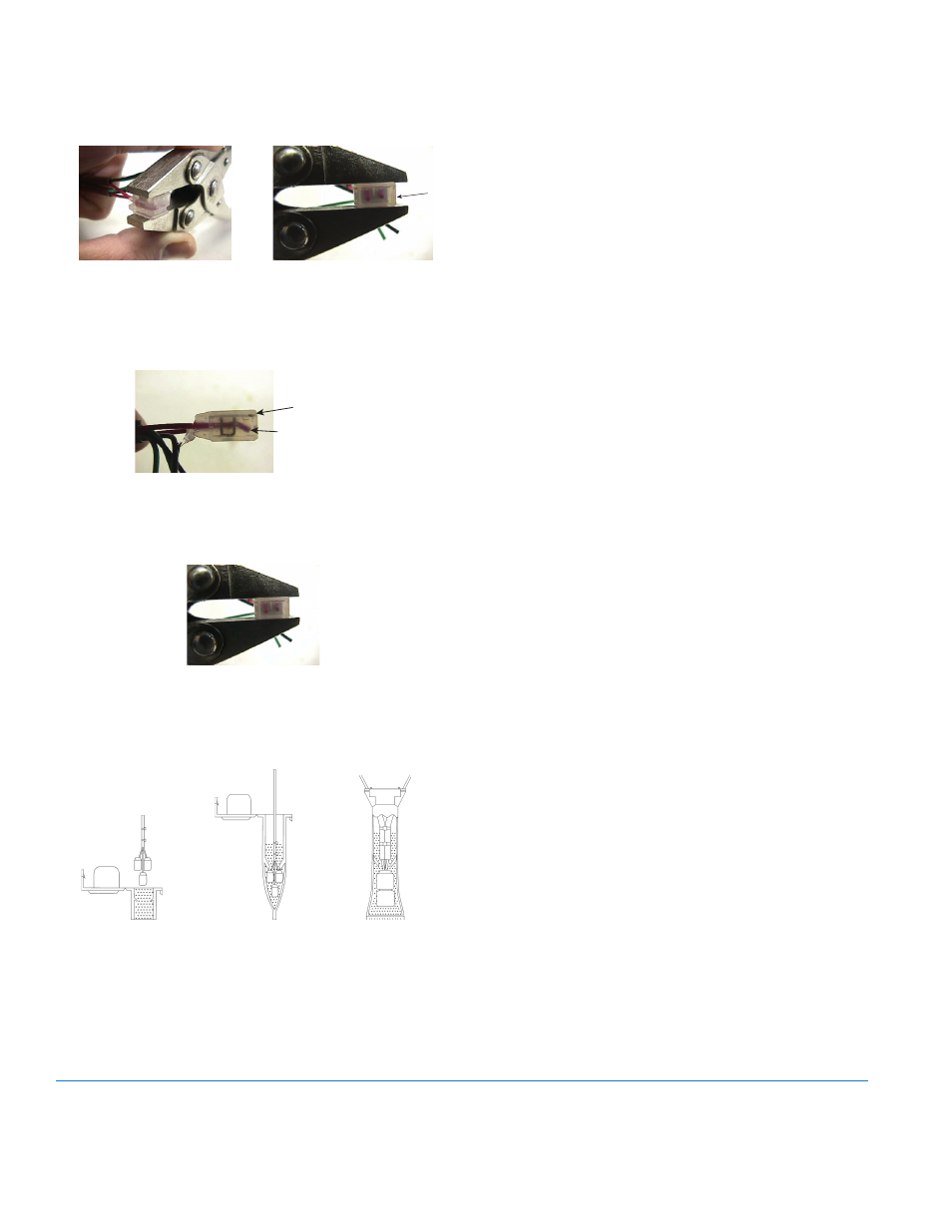
• Crimp the Gel-Connector using the Crimping Tool making sure
the "plunger" is fully seated (i.e. no visual gap between the "cap"
on the plunger and the shell of the Gel-Connector).
Gel-Connector in the
Crimping Tool
Proper crimp, "plunger"
is fully seated
• Inspect the Gel-Connector to ensure that the conductors did not
back out during crimping and that the Gel-Connector "plunger"
is fully seated.
Conductor is to the end
of the gel cap
“Plunger” is fully seated
Conductors are still all the way through to the end of the
Gel-Connector and the "plunger" is fully seated.
• Repeat this procedure for the remaining like color conductors.
PIT INSTALLATIONS
Insert the entire splice assembly into the filled splice tube
62085-001, as indicated in the figure below. Close the cover with
leads exiting alternate sides as indicated in the drawing.
Splice enclosure assembly
ADE WITH TERMINAL SCREWS
OTEE:
N
The ADE with optional terminal screws is suitable for
indoor installation only.
The terminal screws are identified by the letters “R”, “B” and “G”
(standing for Red, Black and Green) molded into the screw cavity.
Strip approximately 1.5 inch of outer insulation sheath using the
59989-001 coax stripping tool. Use caution in removing the outer
sheath so that the inner wire insulation is not damaged.
Unwind the outer foil shield from the cable and cut it off even with
the outer sheath using the wire cutting pliers. Cut the un-insulated
shield drain wire even with the outer sheath using the wire
cutting pliers.
Strip approximately 0.5 inch of insulation from the inner wires
using the 59993-001 Wire Stripper. Use a screwdriver to loosen the
terminal screws sufficiently to allow the bare wire ends to fit below
the screw heads. Bend the bare wire ends into hook shapes that
will closely fit around the shafts of the terminal screws, and hold
the hooks around the screw shafts while tightening the screws
with the screwdriver. Do not overtighten screws. The hooks should
be oriented with the openings to the right, so that tightening the
screws (by turning to the right) will tend to draw the wire closer to
the screw.
Place plastic cable tie, 34776-001, approximately 0.25 inch from the
end of the outer insulation sheath. Tighten securely for strain relief.
Remove excess cable tie. Ensure that the cable exits the terminal
screw cavity via the opening on the right side of the cavity wall and
that the cable tie resides on the interior of terminal cover. Place the
cover over the terminal screw cavity and secure by tightening the
Torx screw.
TESTING
After connections are complete, test the entire installation including
the ADE, wiring and remote or pit module for proper operation in
accordance with the instructions supplied with the module.
Install the ADE on the water meter and secure it using the Torx
screw provided.
LICENSE REQUIREMENTS
This device complies with Part 15 of the FCC Rules. Operation of
this device is subject to the following two conditions: (1) This device
may not cause harmful interference, and (2) this device must accept
any interference received, including interference that may cause
undesired operation. Any changes made by the user not approved
by Badger Meter can void the user’s authority to operate the
equipment. No license is required by the utility to operate an ADE
meter reading system.