Badger Meter Recordall Compound Series Meters User Manual
Page 9
UPSTREAM AND DOWNSTREAM VALVES MUST BE CLOSED BEFORE ATTEMPTING TO REMOVE METER HEAD OR
COVER FROM HOUSING OR PERFORMING ANY SERVICE/MAINTENANCE REQUIRING DISASSEMBLY. FAILURE TO
DO SO CAN LEAD TO HEAD OR COVER BEING "EJECTED" FROM HOUSING, CAUSING PERSONAL INJURY AND/OR
PROPERTY DAMAGE!
1 . Loosen each of the head or cover bolts about one and one- half turns . Do not completely remove the bolts .
2 . If the O-ring between the meter head/cover and the housing is secure and not leaking, pry the measuring element
assembly loose by inserting a screwdriver blade where the head and housing join together .
BE SURE THAT ANY WATER COMING OUT OF THE METER HEAD DOES NOT SPRAY ONTO ELECTRICAL EQUIPMENT TO
CREATE A SHOCK HAZARD.
3 . Allow the meter to drain and relieve internal pressure .
4 . When pressure is relieved, remove the head bolts . Lift the measuring element assembly from the housing .
For specific maintenance of the Turbo Head, see the Recordall Turbo Series Meter User Manual .
5 . When service is complete, start up the system as noted in
“Performance Checks and System Startup” on page 7
Check Valve
Periodic preventive check valve maintenance is highly recommended and should be practiced according to schedule to
assure continuous accuracy and trouble-free performance of your check valve . The valve is water lubricated and should be
regularly inspected for corrosion, obstructions in the waterways and for freedom of movement for all working parts . The
frequency of the inspections is dependent upon the quality of the water supply and authority having jurisdiction . Make sure
all equipment is adequately protected to prevent freezing and physical damage . Repair all leaks .
To remove or replace the knuckle joint assembly, follow these steps:
1 . Shut down the water system and lock it out, if possible .
2 . Loosen the vent screw in the lid slowly to relieve system pressure .
3 . Loosen and remove all inspection port bolts and remove the lid and gasket from valve .
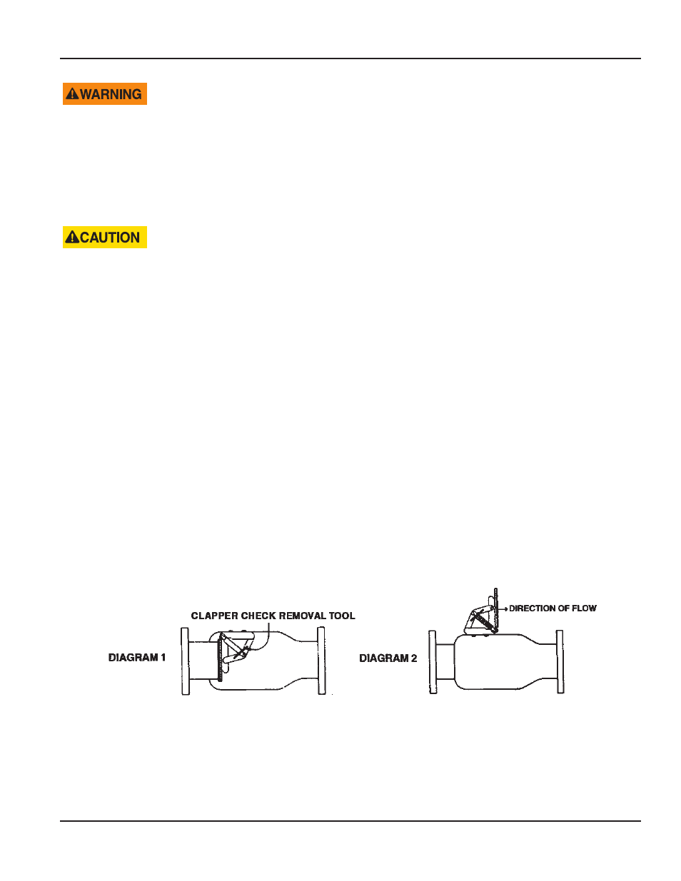
4 . Install proper size clapper check removal tool (see diagram 1 in
and Item 10 in
) . Be sure tool is pushed
to within 1/2" of linkage .
Figure 3: Clapper check removal tool
5 . Loosen equally the two knuckle joint mounting bolts until assembly is free . As bolts are loosened, the linkage will
release slightly and lock the clapper retainer tool in place .
6 . Remove the knuckle joint from the body assuring the clapper retainer tool is not disturbed, as the preloaded knuckle
joint springs have considerable tension in this position .
7 . Bolt the knuckle joint to the outside of the body using the new 3/8" bolts supplied with the new knuckle joint (see
diagram 2) .
User Manual
Page 9
October 2013