Optional extras, General description – Airedale Air Cooled Condensers R407C User Manual
Page 7
CONDENSERS
C11 - 45 / CS50 - 105
Condensers
7
Installation and Maintenance Manual: 6259642 V1.2.0 10/2013
General Description
OPTIONAL EXTRAS
Corrosion Resistant
Coated Coils
In atmospheres where high corrosion is anticipated, epoxy coated aluminium finned coils
can be supplied.
Head Pressure Control -
Variable Speed
(Standard on CS50 - 105)
Head pressure control is maintained via fan speed modulation. This is a more accurate
form of control and will prolong the life of the fan. The controller is rated to IP54 for
outdoor use and will operate accurately in ambients down to -20°C.
Shut Off Valves
Where unit isolation for easier maintenance is required, shut off valves can be supplied
loose for on site fitment.
Short Case Axial Fans
Short case axial fans can be supplied for indoor installations where discharge air requires
to be ducted to an outdoor location. The fans will meet duty plus 75Pa of external static
pressure.
Coil Guards
Sizes 50 - 105 Only
Guards can be fitted to each of the outer coils to protect against damage.
Electronically
Commutated (EC)
Fan Motor
(CS50-105 Only)
ES
EC motors are DC motors with integrated AC to DC conversion; this gives the flexibility
of connecting to AC mains with the efficiency and simple speed control of a DC motor.
The EC fan offers significant power reduction in comparison with equivalent AC fan at
both full and modulated fan speeds. The inbuilt EC fan control module allows for fan
speed modulation from 15-100%, a standard ac fans modulating range is typically 40-
100% of full fan speed.
The EC fan presents superior energy efficiency, at part load fan speeds compared to
the equivalent ac fan motor, offering typical efficiency savings up to 70%.
Fan speeds are factory set to either 1080 rpm, 980 rpm or 700 rpm depending on
sound level variant..
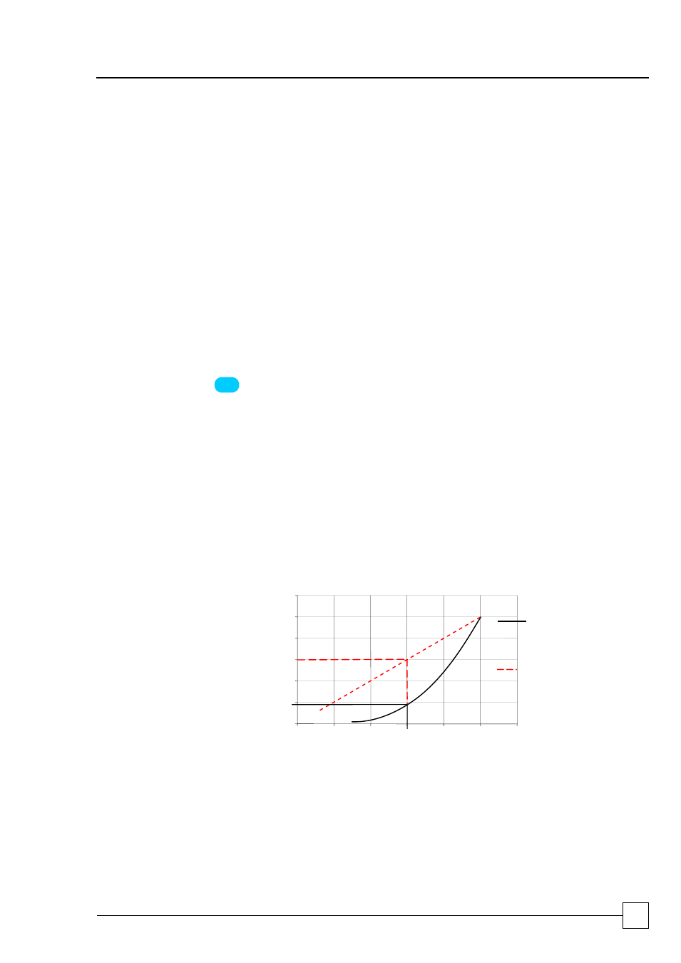
Standard voltage regulated (VR) fan speed controllers offer a linear response. By
comparison the EC fan is adjusted on demand via the unit microprocessor with
precision, offering substantial energy savings. The following illustration shows a
comparison of the typical power input required by each method.
In
pu
t Po
w
e
r %
0
20
40
60
80
100
120
0
20
40
60
80
100
120
Key
EC (Electronically
Commutated) Fan
Speed Control
Voltage Regulated
(VR) Fan Speed
Control
Fan Speed %
Example:
Fan speed of 60%
VR input power required 60%
EC input power required 18%