Refrigeration schematic, Standard recommended installation, Optichill chillers – Airedale OptiChill FreeCool 500kW - 1365kW User Manual
Page 24: Installation data
OPTICHILL
Chillers
24
Chillers
Installation & Maintenance : 6564868 02/2013
Installation Data
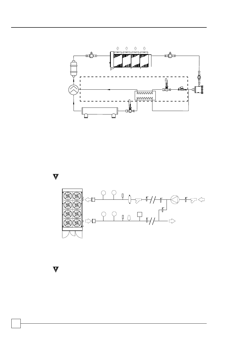
REFRIGERATION
SCHEMATIC
A1
7
9
1
6
5
4
A
3
A2
8
2
1
Screw compressor
7
Solenoid valve
2
Muffler (DQ Only)
8
EEV
3
Ball Valve - Discharge
9
Evaporator
4
Ball Valve - Liquid
A
Economiser Circuit
5
Sight Glass
A1
EEV
6
Filter driver - Replaceable core
A2
Heat exchanger
STANDARD RECOMMENDED INSTALLATION
(Parts Supplied by Others)
GENERAL
The following diagram illustrates the minimum component installation requirements. A
wide range of optional extras are available to suit various applications, please refer to
, on page 10 for details.
CAUTION
The following installation recommendations should be adhered to. Failure to do
this will invalidate the chiller warranty.
P
T
(10)
(9)
(4)
(7)
(3)
(2)
(1)
(6)
(8)
(11)
(12)
T
P
(5)
(1) Flexible connections
(2) Pressure gauges
(3) Temperature gauges
(4) Binder points
(5) De-aerator (optional extra)
(6) Auto air vent (at highest point)
(7) Strainer (optional extra)
(8) Flow switch
(9) Shut off valves
(10) Bypass circuit (for flushing)
(11) Pump
(12) Pump strainer
CAUTION
Full design water flow MUST be maintained at all times. Variable water volume is
NOT recommended and will invalidate warranty
The correct operation of the flow proving device is critical if the chiller warranty is
to be valid.
Following components are fitted within the chiller unit as standard:
Temperature Sensors
Drain Point
Auto Air Vent