Size 1, Cv tmax, Factory serial number label – Warren Controls 377 Float Cage User Manual
Page 9: Flow diagram plate, Part number & serial number, Flow direction, Valve attributes
9
Level COntrols - IOM 377 Float Cage/326L & 322L Lever Valves 377_326L_322L_IOM_RevAa1112
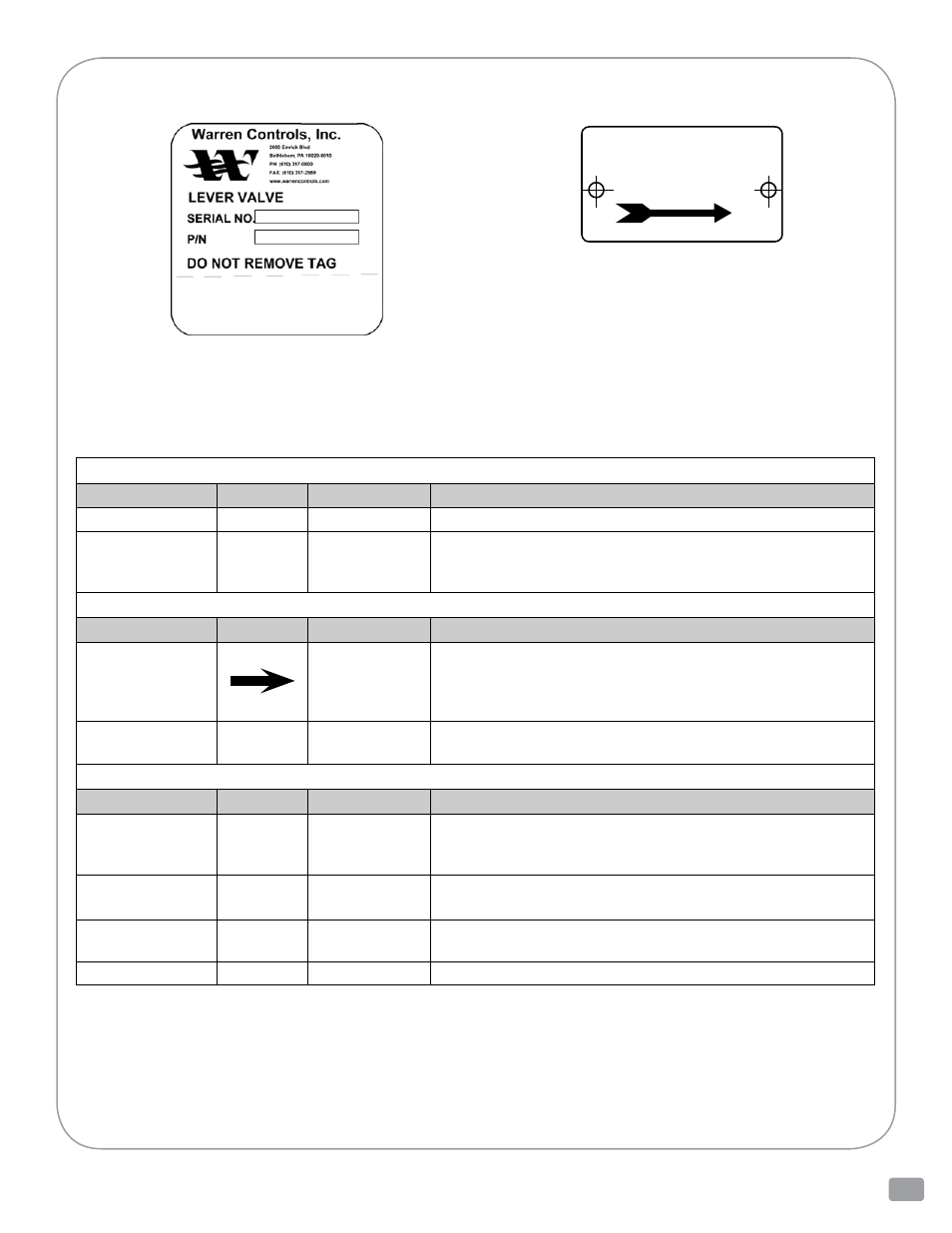
FACTOry SeriAL NumBer LABeL
Information Present on 326L Lever Valves
There is a great deal of information present on each lever valve ranging in importance from the part number and serial
number to casting numbers. This information is important for identifying the valve, installing it correctly, and obtaining
parts.
Examples of the current factory serial number label used on bronze and stainless steel ½ thru 2 inch
326L Lever Valves and the flow diagram plate used on stainless steel ½ thru 2 inch 326L Lever Valves are
shown here. The accompanying table identifies the information present and where to find it on the lever valve. There
may also be other casting numbers and foundry marks present that do not provide useful information. Customer
specific tagging may also present. The labels or plates used, and information present, on Warren Controls other
product lines or older valves may be different, contact the factory for details.
Factory Serial Number Label
Flow Diagram Plate
Flow Diagram Plate
For 326L
Stainless Steel Valves
Size ½ thru 1
(P/N B1670601for
Size 1 Shown)
INFORMATION PRESENT ON 326L LEVER VALVES
BRONZE OR STAINLESS STEEL 1/2 THRU 2 INCH
Part Number & Serial Number
Information
Symbol(s)
Location
Notes
Part numbers
P/N’S
On actuator
•
On
Factory Serial Number Label attached to actuator.
Serial number
SERIAL
NO.
On actuator
and valve
body
•
On
Factory Serial Number Label attached to actuator.
•
Sales order number only stamped on valve body end connection.*
* Number stamped using approximately 1/8 inch tall characters
Flow Direction
Information
Symbol(s)
Location
Notes
Flow direction
through valve
On valve
body
•
On
Flow Diagram Plate attached to mounting boss on valve body between the end
connections (S/S valves ½ thru 1 inch).
•
Arrow cast on valve body between the end connections (2-way S/S 1-1/4 thru 2 inch).
Inlet location
INLET
On valve
body
•
Stamped on valve body inlet end connection (2-way bronze valves ½ thru 2 inch & S/S
valves 1-1/4 thru 2 inch).
Valve Attributes
Information
Symbol(s)
Location
Notes
Maximum
temperature
rating
of valve body
Tmax
On valve
body
•
On
Flow Diagram Plate attached to mounting boss on valve body between the end
connections (S/S valves ½ thru 1 inch).
Trim Cv
(Flow coefficient)
Cv
On valve
body
•
On
Flow Diagram Plate attached to mounting boss on valve body between the end
connections (S/S valves ½ thru 1 inch).
Valve size
SIZE
On valve
body
•
On
Flow Diagram Plate attached to mounting boss on valve body between the end
connections (S/S valves ½ thru 1 inch).
Valve body
material
On valve
body
•
If CF8M is cast on the valve the valve body material is 316 stainless steel.
iNFORmATiON PRESENT ON 326L LEvER vALvES
BRONZE OR STAiNLESS STEEL 1/2 ThRU 2 iNCh
FLOw diAgrAm PLATe
Cv
Tmax
SIZE 1
D
Flow Diagram Plate
For 326L
Stainless Steel Valves
Size 1/2 thru 1
(Size 1 Shown)
PART NUmBER & SERiAL NUmBER
InformatIon
Symbol(S) locatIon
noteS
Part number
P/N
On actuator
• On Factory Serial Number Label attached to actuator.
Serial Number
SERiAL NO.
On actuator
and valve body
• On Factory Serial Number Label attached to actuator.
• Sales order number only stamped on valve body end connection.*
* Number stamped using approximately 1/8 inch tall characters
FLOw DiRECTiON
InformatIon
Symbol(S) locatIon
noteS
Flow direction
through valve
On valve body
• On Flow Diagram Plate attached to mounting boss on valve body
between the end connections (S/S valves ½ thru 1 inch).
• Arrow cast on valve body between the end connections
(2-way S/S 1-1/4 - 2 inch).
Inlet location
iNLET
On valve body
• Stamped on valve body inlet end connection (2-way bronze valves
½ thru 2 inch & S/S valves 1-1/4 thru 2 inch).
vALvE ATTRiBUTES
InformatIon
Symbol(S) locatIon
noteS
Maximum
temperature rating
of valve body
Tmax
On valve body
• On Flow Diagram Plate attached to mounting boss on valve body
between the end connections (S/S valves ½ thru 1 inch).
Trim Cv
(Flow coefficient)
Cv
On valve body
• On Flow Diagram Plate attached to mounting boss on valve body
between the end connections (S/S valves ½ thru 1 inch).
Valve Size
SiZE
On valve body
• On Flow Diagram Plate attached to mounting boss on valve body
between the end connections (S/S valves ½ thru 1 inch).
Valve Body Material
On valve body
• If CF8M is cast on the valve the valve body material is 316 stainless steel.