Installation guidelines – Warren Controls 377 Float Cage User Manual
Page 5
5
Level COntrols - IOM 377 Float Cage/326L & 322L Lever Valves 377_326L_322L_IOM_RevAa1112
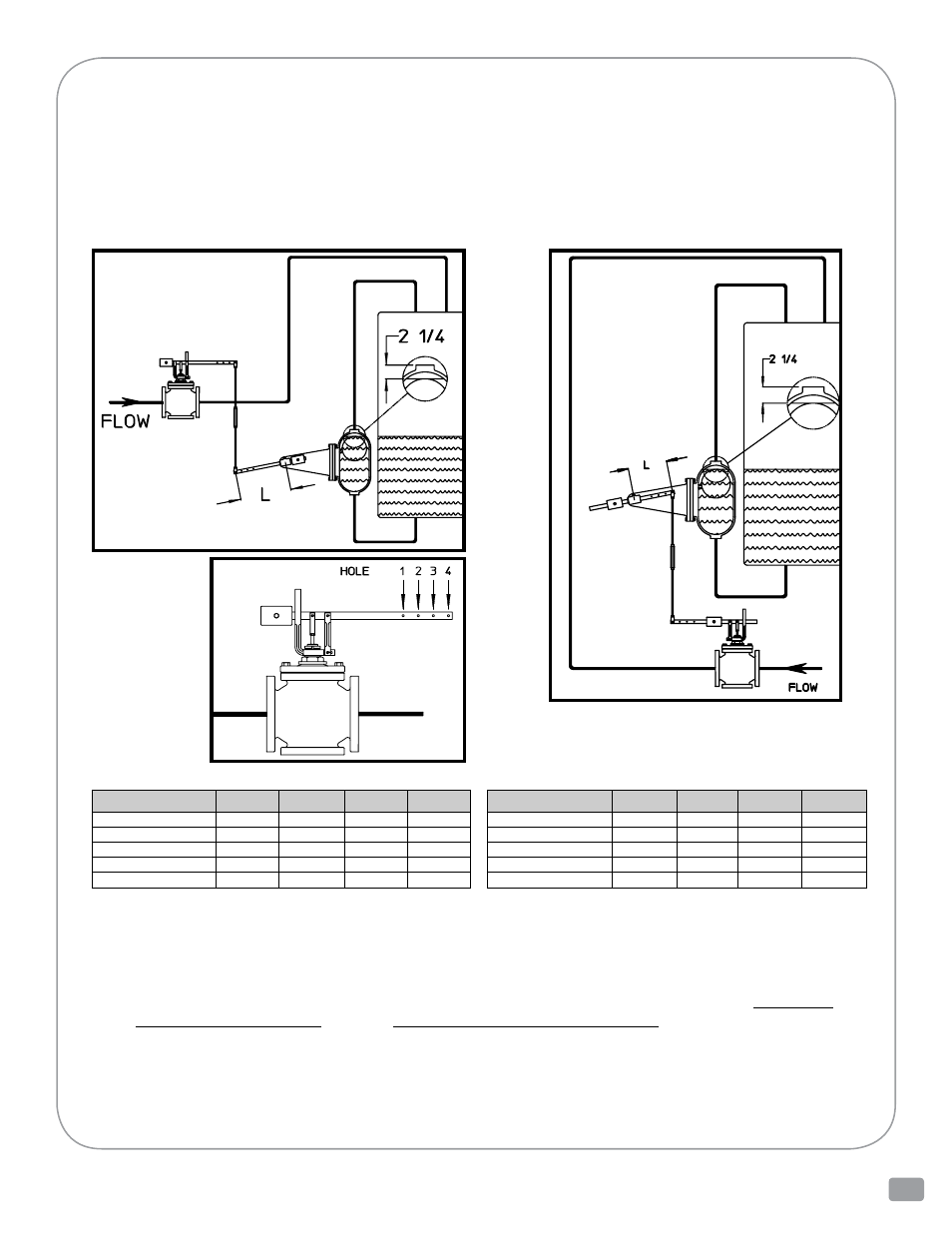
dImEnSIon L - rISIng LEVEr oPEnS VALVE
iNSTALLATiON GUiDELiNES
bEForE you bEgIn
The guidelines presented here are for a typical tank filling application utilizing a 377 Float Cage and a Warren
Controls Lever Valve. As shown in the Typical Installation drawings the 377 closes the Lever Valve when the
water in the tank reaches the desired level. Since there are numerous possible working configurations it is nec-
essary for you to determine where the 377 and Lever Valve will be located before you install them. The InSTAL-
LATIon guIdELInES are presented for this purpose. Please read all guidelines thoroughly before you begin
The 377 when installed according to these guidelines will provide a maximum water level in the tank that is
2-1/4 inches below the top of the 377. The 377 Float Cage must be installed with the axis through the 1-1/2 nPT
pipe connections oriented vertically. The 326L or 322L Lever Valve is located above the 377 in rising lever opens
valve applications, and below the 377 in rising lever closes valve applications. The lever valve must be installed
with the fluid flowing in the correct direction. For proper operation in all applications, lever valves must be
piped according to the corresponding flow arrows, or inlet markings present on each valve (See Information
Present on 326L Lever Valves section or Information Present on 322L Lever Valves section for location of im-
portant information on valve). The lever valve must be installed in the vertical position with the stem pointing
upward. When the maximum desired water level in the tank is reached the 377 closes the lever valve stopping
the flow of water into the tank. When the lever valve is closed its lever is horizontal, the turnbuckle is vertical, the
end of the 377 lever connected to the turnbuckle is at its lowest point in rising lever opens valve applications
and at its highest point in rising lever closes valve applications. Clearance must be allowed for each turnbuckle
connection and lever rotation. There are four possible turnbuckle connecting holes on the lever.
rISIng LEVEr oPEnS VALVE dIAgrAm
rISIng LEVEr CLoSES VALVE dIAgrAm
TurnbuCkLE
ConnECTIng
hoLE
dIAgrAm
dImEnSIon L - rISIng LEVEr CLoSES VALVE
VALVE
HOLE 1
HOLE 2
HOLE 3
HOLE 4
1/2, 3/4 & 1 IN 326L
9
10-1/4
11-3/4
13-1/4
1-1/4 & 1-1/2 IN 326L
13
15-1/4
17-1/2
19-3/4
2 IN 326L
16
18-1/2
21-1/4
NA
1-1/2 & 2 IN 322L
7-1/2
8-3/4
10
11-1/4
2-1/2 & 3 IN 322L
11-1/4
13-1/4
15
17
VALVE
HOLE 1
HOLE 2
HOLE 3
HOLE 4
1/2, 3/4 & 1 IN 326L
7-1/2
9
10-1/4
11-3/4
1-1/4 & 1-1/2 IN 326L
11
13
15-1/4
17-1/2
2 IN 326L
13-1/4
16
18-1/2
21-1/4
1-1/2 & 2 IN 322L
6-1/4
7-1/2
8-3/4
10
2-1/2 & 3 IN 322L
9-1/2
11-1/4
13-1/4
15