Ar ch ive d – Seametrics EX80 Series v.1 User Manual
Page 7
Page 5
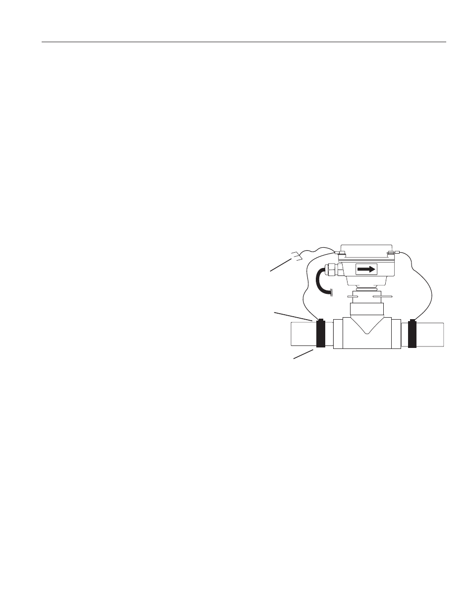
Grounding Guidelines:
•
For best results, use a good quality ear th ground,
such as metallic water piping, or a stake driven
into the ground.
•
If the flow sensor is installed in metallic piping, for
optimum grounding clamp wires to the piping a
shor t distance to either side of the flow sensor
using hose-type clamps. Connect these wires to
the earth ground and to one of the housing screws.
General Electrical Guidelines:
•
Whenever possible avoid running control cables
in the same conduit with AC power. Use shielded
control cable where this type of installation is
necessar y.
•
If using shielded cable, be sure that one end is
grounded
•
Avoid routing flow sensor cables in close proximity
to a variable frequency drive.
•
Recommended power and output wiring is 18-22
AWG control cable, shielded if the run length is
more than 18 feet (6 meters).
•
Recommended voltage is 12-24 VDC. Note that
unregulated power supplies can var y from
nameplate voltage by a considerable amount.
When in doubt, use a regulated power supply.
See the Connections diagrams on the following pages, for
the appropriate terminals.
Power: A 12 - 24 Vdc power supply which is capable of
at least 250 mA current output is needed.
Pulse Output: This open-collector isolated output does
not supply power. It functions like a polarity-sensitive switch
closure. It reaches a maximum of 500 Hz at the maximum
flow rate of 20 feet/second. This pulse is generated in
both for ward and reverse flow directions (see “Direction”
below).
Note: This output is limited to 5 mA at 30 Vdc
maximum.
Direction Indicator: This output is switched by a solid
state relay, which is not polarity sensitive. It is “off” (open)
when flow is in the for ward direction and “on” (closed)
when flow is in the reverse direction.
Note: this output is
limited to 100 mA at 150 Vdc maximum.
ELECTRICAL CONNECTIONS
GROUNDING DIAGRAM
Ground To
Metallic Pipe
Earth
Ground
Hose Clamp
AR
CH
IVE
D
(Includes Dates 6/14/04 to 5/05)