Seametrics IP800-Series User Manual
Page 9
Page 9
MAINTENANCE
Sensor Replacement.
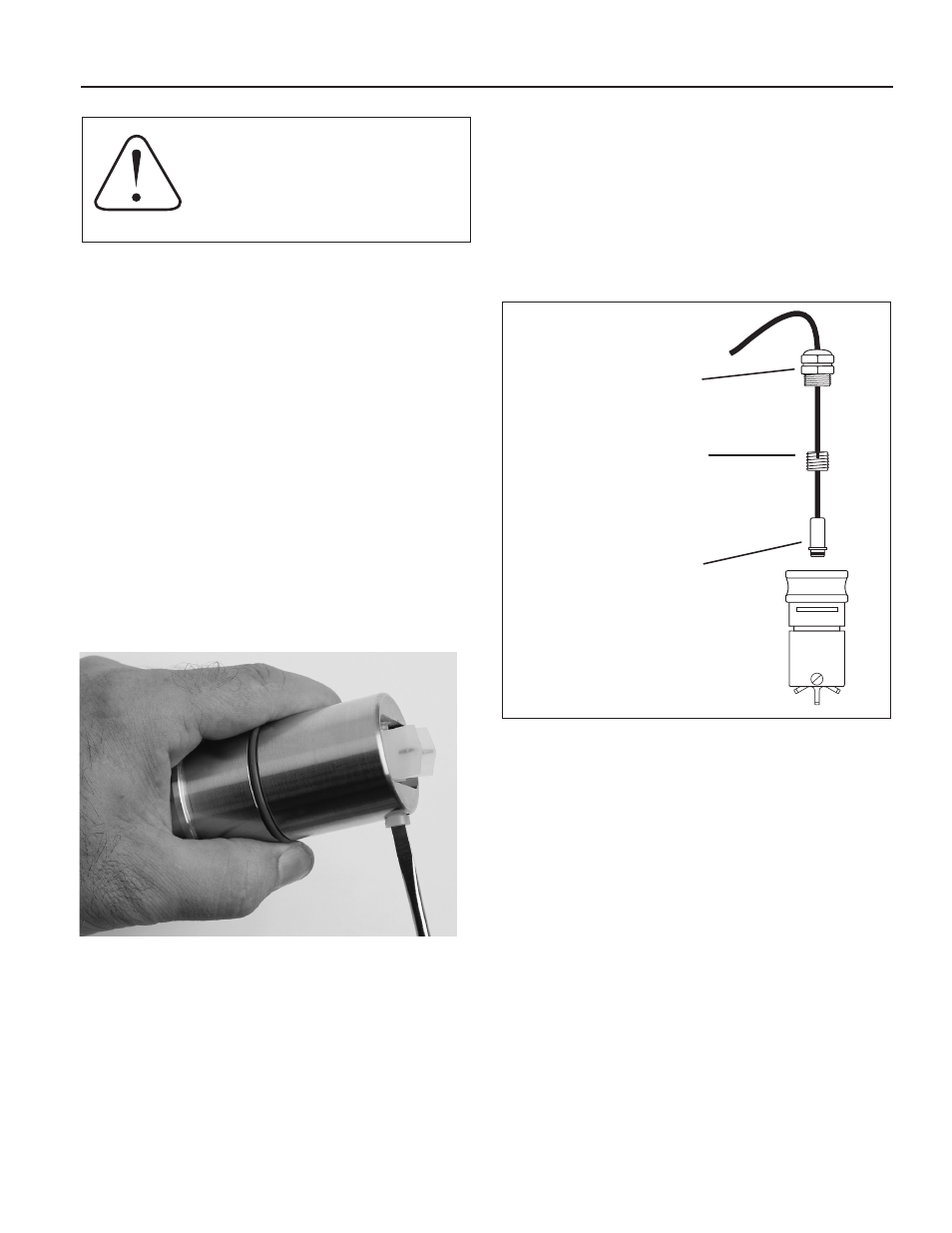
It is very unusual for a sensor to re-
quire replacement in normal use. The primary cause of sensor
failure is overvoltage (inadvertent connection of high voltage,
for example) or incorrect polarity on hookup. The sensor is
replaced by removing the strain relief, then threading out
the sensor retainer plug. Remove the entire sensor capsule
by pulling on the cable. The new sensor capsule can then be
installed. Replace the retainer plug, and then replace and
tighten the strain relief.
Rotor Replacement.
It is unusual for a rotor to require re-
placement due to damage sustained in normal service. More
commonly, the meter is dropped while it is out of the pipe.
Another reason for rotor replacement is shaft wear after long
service. Rotors are easily field-replaced.
To install a rotor, follow these steps:
1. Unscrew the threaded bearing housings to expose
the shaft ends. If bearings are being replaced,
back them completely out.
2. Remove the rotor. Put the new rotor in its place.
3. Thread in one bearing housing part way, then the
other. Take care to start the end of the shaft into
the bearing hole before tightening further.
4. Screw in bearing housings until they bottom.
Note: Do not use excessive force.
5. Check for free spin. Blowing lightly on the rotor
should result in it spinning rapidly and coasting to a
smooth stop.
Caution:
Never remove the u-clip retainer
when the pipe is under pressure. Always
remove pressure from the pipe before at-
tempting to remove the meter. Removal
under pressure may result in damage or
serious injury.
Signal Troubleshooting.
The flow sensor has only one mov-
ing part, the rotor. If this is turning properly and there is no
signal, the magnetic sensor is not operating properly. To check
the signal, apply 12 Vdc power to the red (+) and black (-)
leads. Set a multimeter to voltage reading. Put the positive
multimeter lead on the red wire and the negative lead on the
white wire. Slowly turn the rotor. Voltage reading should swing
between -12 Volts and 0 Volts as the rotor turns. If it does
not, the solid-state magnetic sensor is not working properly.
Checking for continuity is not a useful test of these sensors.
Sensor Replacement
1) Loosen and unthread
Strain Relief
2) Remove Sensor Retainer
Plug by inserting a
screwdriver blade into
one side of the slot and
turning
3) Remove the Sensor
Capsule by pulling on
the cable
4) Reverse the process
to replace