Electronic load, Verification and performance tests - 2, A. b. c – Agilent Technologies 6613C User Manual
Page 13: Figure 2-1. test setup
Verification and Performance Tests - 2
13
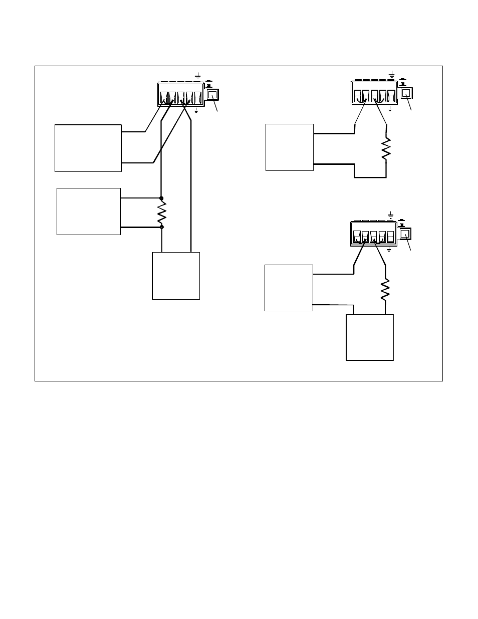
Figure 2-1. Test Setup
Electronic Load
Many of the test procedures require the use of a variable load capable of dissipating the required power. If a variable
resistor is used, switches should be used to either; connect, disconnect, or short the load resistor. For most tests, an
electronic load can be used. The electronic load is considerably easier to use than load resistors, but it may not be
fast enough to test transient recovery time and may be too noisy for the noise (PARD) tests.
Fixed load resistors may be used in place of a variable load, with minor changes to the test procedures. Also, if
computer controlled test setups are used, the relatively slow (compared to computers and system voltmeters) settling
times and slew rates of the power supply may have to be taken into account. "Wait" statements can be used in the
test program if the test system is faster than the supply.
Load
-S
-
+
+S
Local
Remote
SENSE
+
-
50VDC MAX TO
resistor
DC
Ammeter
-
+
Load
-S
-
+
+S
Local
Remote
SENSE
+
-
50VDC MAX TO
resistor
DC
Ammeter
-
+
+
-
External
Set to
Remote
Set to
Remote
DC supply
a.
b.
c.
-S
-
+
+S
Local
Remote
SENSE
+
-
50VDC MAX TO
NOTE: Connector
is removable
Set to
DVM or
Current
monitor
RMS voltmeter
Remote
400 ohm
400 ohm
-
+
Electronic
-
+
DVM, Scope, or
-
+
RMS voltmeter
Load
(for CV tests)
(for CC tests)
Note: Use dc supply with same polarity
connectons for - CC tests.
Replace electronic load with resistors
for CC noise test.
(see note)