5 vdc output connections – Lake Monitors Flow Transmitters User Manual
Page 35
1-5 VDC Output Connections
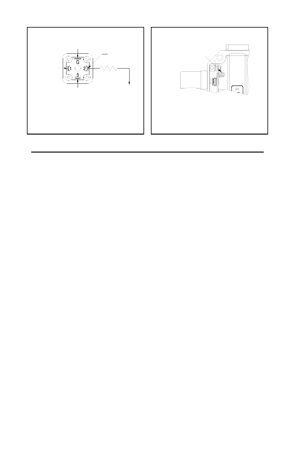
Wiring Instructions (Refer to Illustrations 8 and 9 above):
1) Move the programmable jumper on the signal conditioning board
into the position closest to the meter’s outlet, as shown in
Illustration 9.
2) Connect the positive voltage (+17 to +35 VDC) to terminal #1 of
the din connector.
3) Connect terminal #2 of the DIN to the 1-5 VDC input of the
receiving device.
4) If the power source does not originate at the receiving device, a
wire will need to be connected between the negative side of the
voltage source and the signal ground of the receiving device.
5) If the transmitter is operating properly, the green LED on the
circuit board will illuminate dimly at zero flow and will increase in
intensity as flow rate increases.
Page 35 / Flow Transmitters / Lake Manual
Illustration 8
Illustration 9
NO CONNECTION
ELECTRICAL CONNECTIONS - 1- 5 VDC
NO CONNECTION
249 OHMS
PIN #1
+17 - 35 VDC
PIN #2
1-5 VDC OUT
TO SIGNAL
GROUND
PROGRAMMABLE JUMPER
IN POSITION CLOSEST
TO METER OUTLET
JUMPER POSITION - 1- 5 VDC