General information, Overview, Resistor to the 4-20 ma loop – Lake Monitors Flow Transmitters User Manual
Page 30
NOTE: Installation, operation and cleaning instructions for the basic flow meter
cartridge can be found in the first section of this manual. The following instruc-
tions are specifically for meters equipped with signal conditioning circuitry for
transmitting a proportional output signal.
General Information
Lake’s Flow Transmitters are typically used to transmit a signal
proportional to flow rate to a process control computer, a PLC, a
recorder, or a panel-mount display. The Flow Transmitters are used
as the primary input device to record flow rates through hydraulic and
pneumatic systems.
The universal output transmitter circuit employed by the Lake Flow
Transmitter is capable of producing output signals of 4-20 mA, 0-5
VDC, and 0-2000 Hz square wave pulse. A 1-5 VDC signal may be
obtained by connecting a 249
Ω
resistor to the 4-20 mA loop.
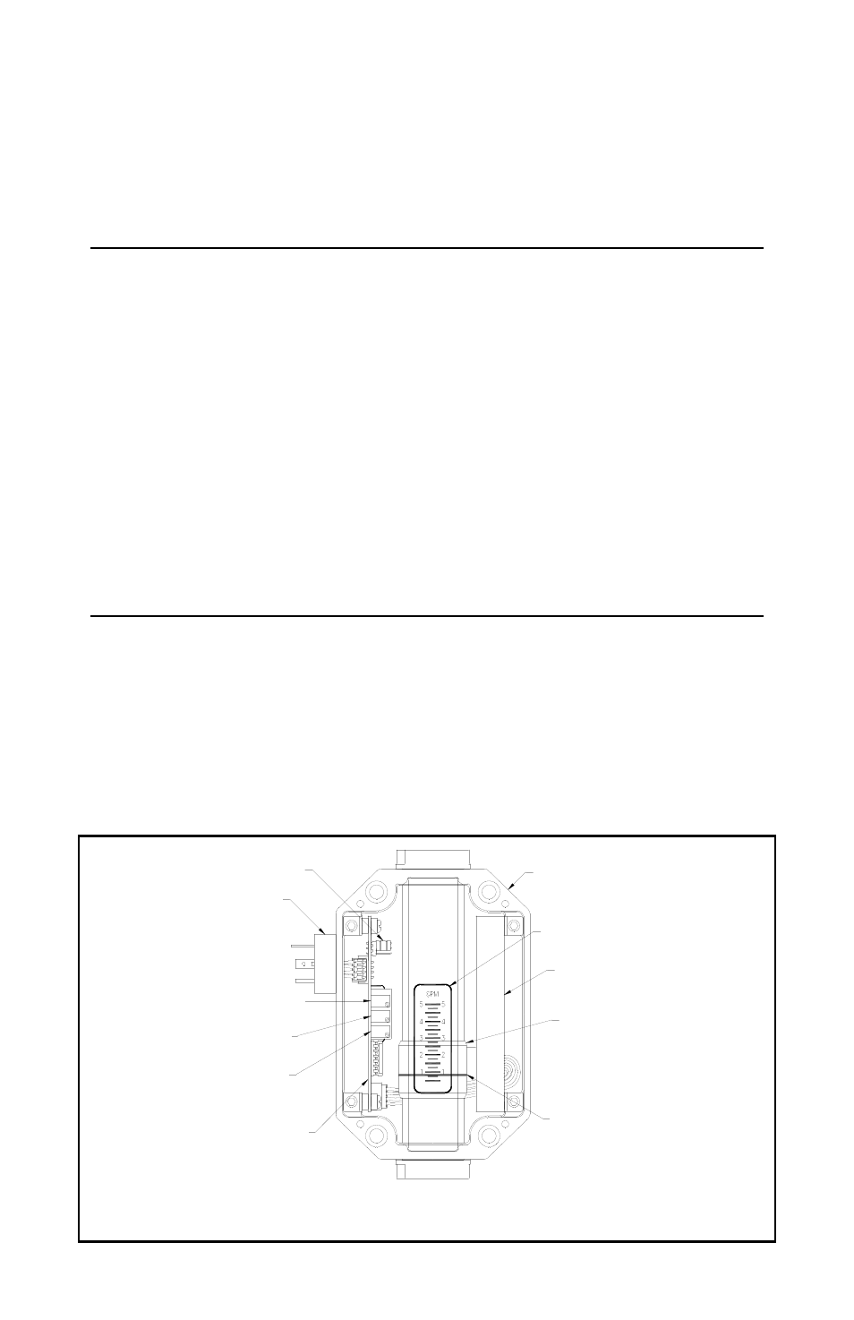
Overview
Illustration 1 shows a Flow Transmitter with the cover removed.
The follower moves in unison with an orifice plate inside of the unit’s
pressure vessel via a magnetic coupling in order to indicate flow rate.
As the follower moves with changes in flow rate, the flow rate is
determined by relating the position of the flow indicator line to the
increments on the flow rate scale.
Page 30 / Flow Transmitters / Lake Manual
Illustration 1
PROGRAMMABLE JUMPER
NEMA 4X ENCLOSURE
SENSOR ASSEMBLY
FOLLOWER
FLOW INDICATOR LINE
FLOW RATE SCALE
DIN CONNECTOR
4-20 mA OFFSET ADJUST
4-20 mA SPAN ADJUST
0-5 VDC SPAN ADJUST
SIGNAL CONDITIONING CIRCUIT