Wiring code: standard single switch, Wiring code: dual switch alarm – Lake Monitors Flow Transmitters User Manual
Page 25
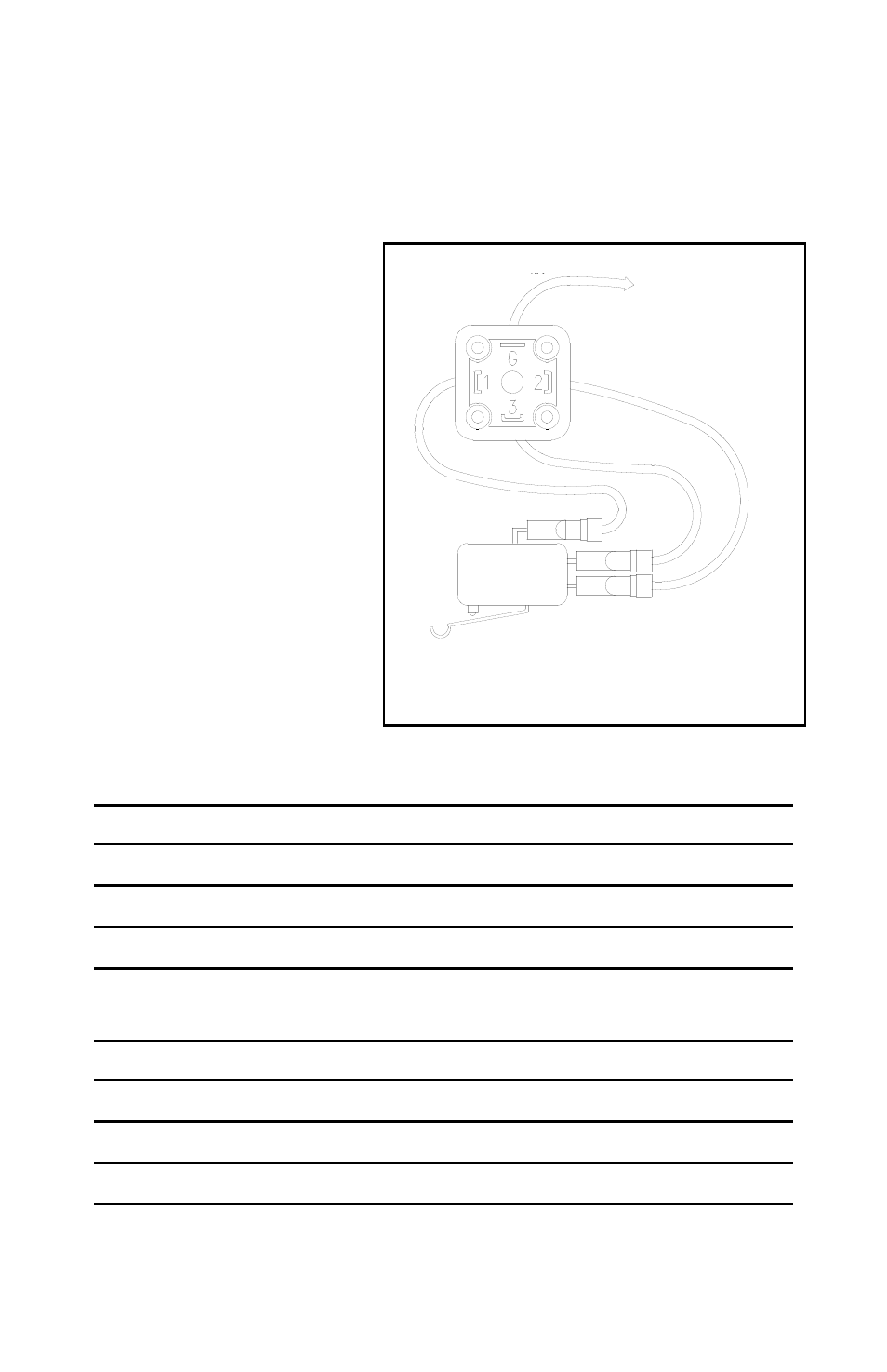
Illustration 7 shows the connections for a standard, single switch
Flow Alarm as they are shipped from the factory. The wiring for other
types of connections are outlined in the tables below. For additional
details, please consult the factory or your authorized Lake distributor.
Alternates to the standard
Hirschmann-type DIN
connector are available on
a custom basis. The Flow
Alarm may be outfitted
with a variety of different
electrical connections
including conduit fittings,
cable-type connectors and
cord grip/pigtail interfaces.
Almost any commercially
available electrical
connector may be used.
If an alternate connector
is desired, please consult
Lake.
Wiring Code: Standard Single Switch
White - Common
Terminal #1of DIN
Black - N.C. Contact
Terminal #2 of DIN
Red - N.O Contact
Terminal #3 of DIN
Green - Enclosure Ground
Terminal “G” of DIN
Wiring Code: Dual Switch Alarm
White - Both Common
Terminal #1of DIN
Black - Decreasing N.O. Contact
Terminal #2 of DIN
Red - Increasing N.O. Contact
Terminal #3 of DIN
Green - Enclosure Ground
Terminal “G” of DIN
Page 25 / Flow Alarms / Lake Manual
Illustration 7
GREEN
NO
NC
BLACK
WHITE
COMMON
RED
TO ENCLOSURE
GROUND