5 vdc output connections – Lake Monitors Flow Transmitters User Manual
Page 33
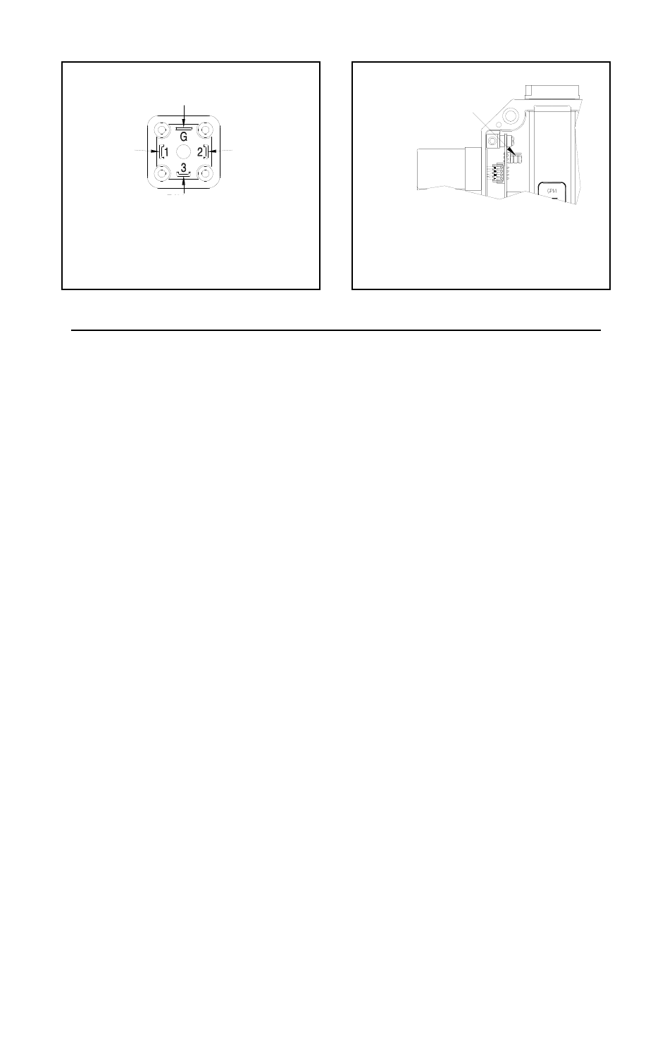
0-5 VDC Output Connections
Wiring Instructions (Refer to Illustrations 4 and 5 above):
1) Move the programmable jumper on the circuit board into the
position closest to the meter’s inlet, as shown in Illustration 5.
2) Connect the positive voltage source (+12 to +35 VDC) to terminal
#1 of the din connector.
3) Connect terminal #2 of the din connector to the negative side of
the DC voltage source.
4) Connect terminal #3 of the din connector to the 0-5 VDC input of
the receiving device.
5) If the power source does not originate at the receiving device, a
wire will need to be connected between the negative side of the
voltage source and the signal ground of the receiving device.
6) If the transmitter is operating correctly, the green LED on the
circuit board will illuminate brightly when power is applied to the
unit.
NOTE: The input impedance (resistance) of the receiving device
must not be lower than 100W or non-linearities may result.
Lower impedance will not damage the transmitter.
Page 33 / Flow Transmitters / Lake Manual
Illustration 4
Illustration 5
PROGRAMMABLE JUMPER
IN POSITION CLOSEST
TO METER INLET
JUMPER POSITION - 4-20 mA
PIN #3
0 - 5 VDC OUTPUT
ELECTRICAL CONNECTIONS - 0 - 5VDC
NO CONNECTION
PIN #1
+12 - 35 VDC
PIN #2
DC GROUND