KYORITSU 6201A User Manual
Page 7
— 5 —
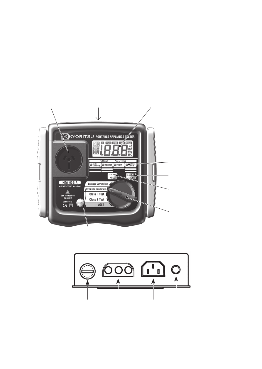
Fig. 3
⑴
Test socket ⑵ Terminal block ⑹ LCD
⑺
LED for test result
⑻
Start/Stop switch
⑼
Null/250V-500V
switch
⑽
Function switch
⑾
SELECT switch
3.3 Features
• Warning for the appliance to be ON.
• Selection for 250V or 500V on the insulation resistance test.
• Null function for the protective conductor resistance test.
• Warning for the over range value in the LCD.
• Capable of judging pass/fail of tests by LED on the panel and by buzzer.
3.4 INSTRUMENTS LAYOUT
Terminal Block
⑿ ⑶ ⑷ ⑸
⑴
Test socket
Insert the mains plug of DUT to this socket for the polarity test of protective
conductor resistance, insulation resistance and Leakage current test.
See also other documents in the category KYORITSU Tools:
- 1009 (13 pages)
- 1011 (12 pages)
- 1012 (12 pages)
- 1018 (1 page)
- 1030 (1 page)
- 1061 (58 pages)
- 1051 (40 pages)
- 1109S (36 pages)
- 1110 (1 page)
- 2000 (1 page)
- 2002PA (27 pages)
- 2007A (1 page)
- 2009R (33 pages)
- 2012R (2 pages)
- 2017 (1 page)
- 2031 (1 page)
- 2033 (9 pages)
- 2040 (2 pages)
- 2046R (2 pages)
- 2200 (3 pages)
- 2210R (1 page)
- 2300R (1 page)
- 2413F (24 pages)
- 2413R (24 pages)
- 2431 (2 pages)
- 2432 (1 page)
- 2433R (1 page)
- 2434 (10 pages)
- 2500 (1 page)
- 2608A (2 pages)
- 3005A (24 pages)
- 3021 (24 pages)
- 3121A (12 pages)
- 3126 (28 pages)
- 3127 (60 pages)
- 3128 (88 pages)
- 3131A (20 pages)
- 3132A (20 pages)
- 3161A (24 pages)
- 3321A (24 pages)
- 4105A (10 pages)
- 4106 (48 pages)
- 4116A (20 pages)
- 4140 (32 pages)
- 4200 (24 pages)