KYORITSU 6201A User Manual
Page 23
— 21 —
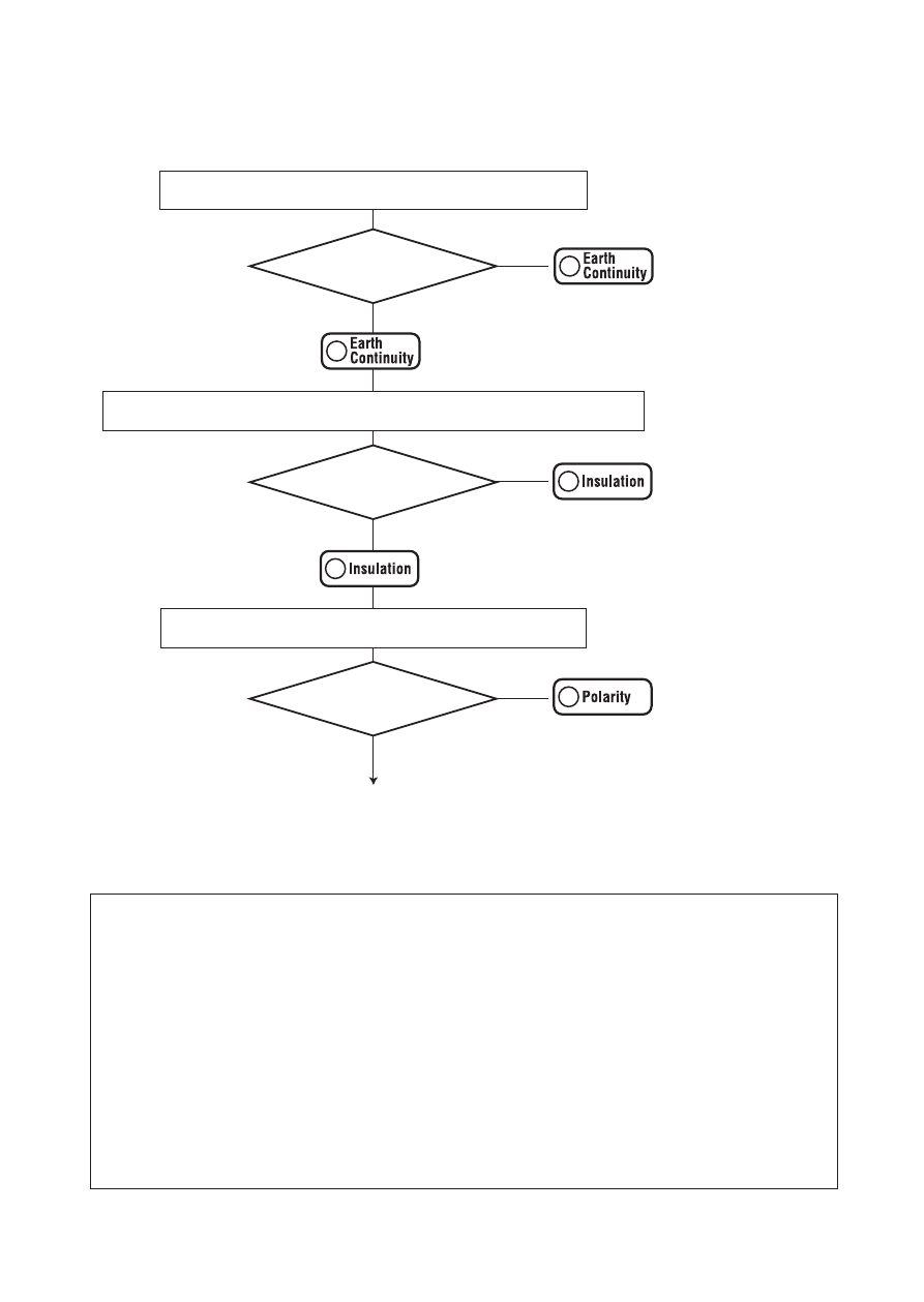
Extension Leads Test Flowchart
Start
#
CAUTION
• Short-circuit between L/N and PE is doubt when "no" and "OFF"
appears on the LCD in turns at the insulation resistance measurement
of the Extension leads test for Class I & II while DUT is on. Testing
should be immediately suspended.
• Follow the procedure described in 5.2-3 and do Null setting before a
measurement.
• When the terminal is open or the resistance value exceeds measuring
range, “OL” mark (over range display) appears on the LCD.
• Do not touch the device under test while testing is in progress. Since
a high voltage of 500V, user may get electrical shock.
(1). Protective conductor resistance test.
RPE <
= 1Ω?
(2). Insulation resistance test between L/N and PE.
(3). Polarity test between L-L and N-N.
L-L & N-N <
= 10Ω?
Light up in red
“
no” →“Con”→“value” will
be repeated on the LCD.
Light up in red
“
no” →“LnE”→“value” will
be repeated on the LCD.
Light up in red
“
no” →“L-L” →“value” or
“
no” →“n-n” →“value” will
be repeated on the LCD.
Value of (1) and (2) will be
alternately displayed on LCD.
No
No
No
Yes
Yes
Yes
PASS
Light up in green
Light up in green
LnE >
= 1MΩ?