KYORITSU 6010B User Manual
Page 20
● Impedance of the power transformer secondary winding.
● Impedance of the phase conductor resistance from the power transformer to
the location of the fault.
● Impedance of the protective conductor from the fault location to the local
earth system.
● Resistance of the local earth system (R).
● Resistance of the power transformer earth system (Ro).
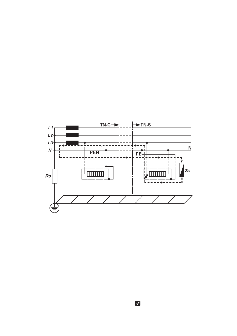
For TN systems the earth fault loop impedance is the sum of the following
impedances (See Fig 10):
Fig 10
● Impedance of the power transformer secondary winding.
● Impedance of the phase conductor from the power transformer to the location
of the fault.
● Impedance of the protective conductor from the fault location to the power
transformer.
7.3 Automatic over-temperature cut-out
During the short test period the instrument dissipates power of about 6 kW. If
frequent tests are conducted over a prolonged period of time, the internal test
resistor will overheat. When this happens, further tests are automatically
inhibited and the over-temperature symbol " " appears in the display. The
instrument must then be left to cool down, when testing may be resumed.
― 18 ―