KROHNE BM 100A EN User Manual
Page 21
Installation and operating instructions BM 100 A
21
3 User
Interface
The BM 100 A may be configured and operated using a user interface set into the signal converter
housing or a remote link.
3.1
Power On and self-test mode
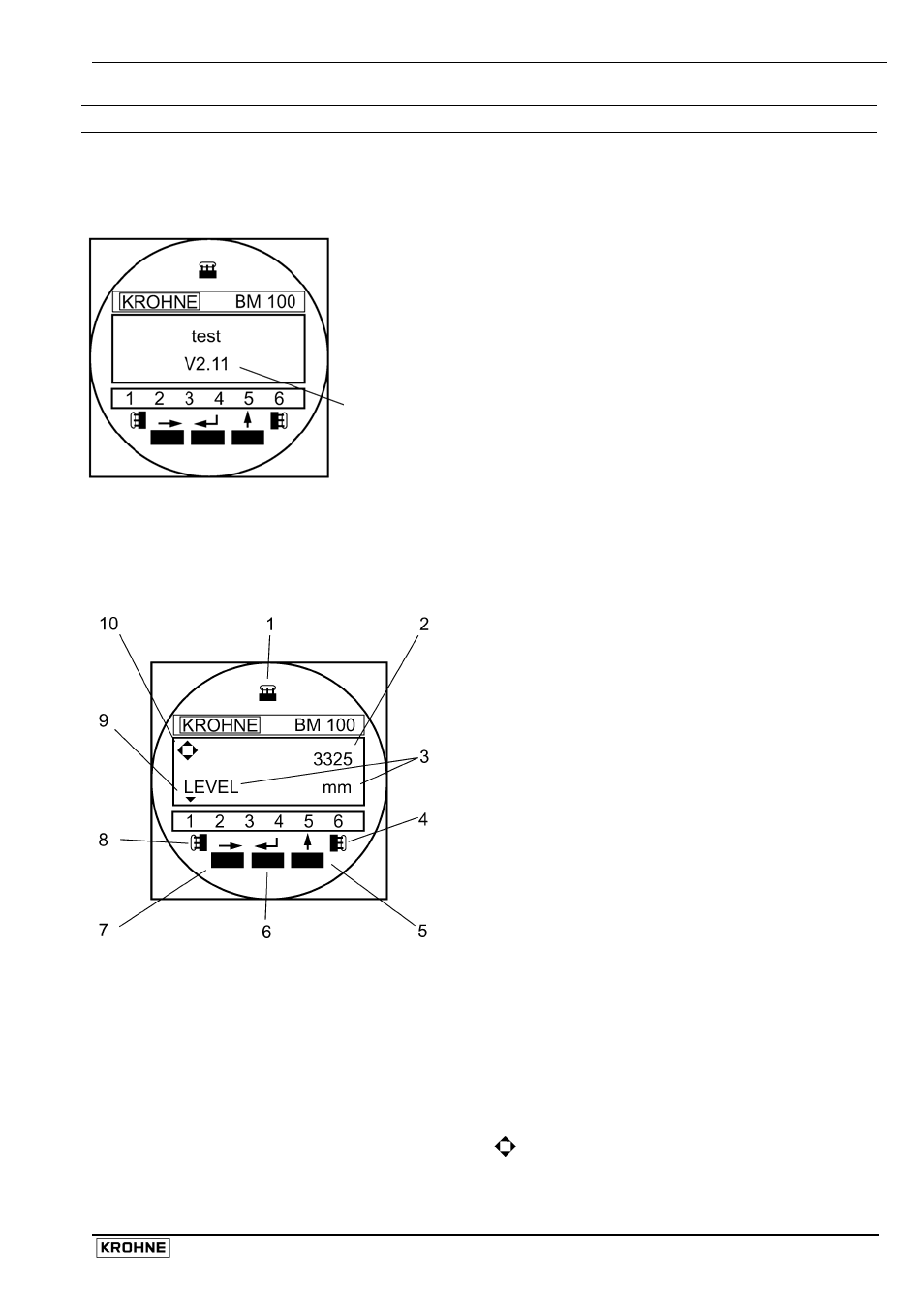
The BM 100 A automatically self-tests once connected to a power
source. The screen readout shown on the left will be displayed.
This test takes from 20 seconds to 1½ minutes to complete.
The local display will then switch over to the operation mode
display shown below.
Firmware release programmed into the EPROM (Electrically
Programmable Read Only Memory)
3.2
Local user interface
The BM100A Local user interface is simple to use. It has three push-buttons, three magnetically-
keyed sensors for configuring the gauge without removing the front cover in hazardous zones and
a three-line LCD (Liquid Crystal Display) screen at the front of the signal converter housing.
1
ENTER Hall Sensor:
Keyed using a bar magnet. As item 6.
2
First Display Line:
Operating mode - measurement value
Configuration mode - function number
3
Second Display Line:
Operating mode - item measured and units
Configuration
mode
-
function definition
4
UP Hall Sensor:
Keyed using a bar magnet. As item 5.
5
Press the UP push-button:
• To increase the value of a selected digit
• For password definition: code U or ↑
6
Press the ENTER push-button:
• To go back a step in the menu
• To validate data entered
• For password definition: code E or ↵
7
Press the RIGHT push-button:
• To enter configuration mode
• To move cursor right in configuration mode
• For password definition: code R or →
8 RIGHT Hall Sensor:
Keyed using a bar magnet. As item 7.
9 Status Markers:
See the next page for details.
Note: the display screen will go blank
below –20°C / –4°F but data can still be
displayed if the instrument is connected
to a computer with PC STAR or other
remote link.
10 Key register symbol:
Enter pressed
↑
Up pressed
→
Right pressed