Modbus protocol, 2 data representation – KROHNE UFC 400 Modbus EN User Manual
Page 9
MODBUS PROTOCOL
5
9
UFC 400
www.krohne.com
05/2013 - 4002744801 - AD Modbus UFC 400 R01 en
5.2 Data representation
There are two data types used to transmit information on a Modbus data bus, the "Bit" and the
"Register". The "Bit" represents a single binary state, whether as an output or an input condition.
The "Register" is a 16-bit integer transmitted as two 8-bit characters. Using multiple "Registers"
the Modbus interface can transmit higher accuracy values such as "Floating Point" and "Double
Precision Floating Point" numbers.
"Bit" variables are packed into a byte containing 8 bit, so each character, sent or received, can
contain up to 8 "Bit" variables. The master and slave devices use only as many 8 bit data
characters as are required to transmit the information. Any unused bits in the data characters
are ignored. The bit that is requested by the start address is transmitted in the LSB at bit 0. The
next "Bit" value is transmitted in the next bit (bit 1). This continues until the last bit location (bit 7)
of the LSB is reached. The next "Bit" value is then transmitted in the next data byte (LSB+1/MSB)
at bit 0. This continues until all of the requested values have been transmitted. Any unused bits in
the MSB are filled out with "0"s.
For simple single register variables the MSB of the register is transmitted first, with the LSB
following immediately after. However, for variables that require multiple registers, i.e. the
"Floating Point" and "Double Precision Floating Point" variables, the transmission order can be
selected in the RS485 settings. By default, those values will be transmitted in Big Endian.
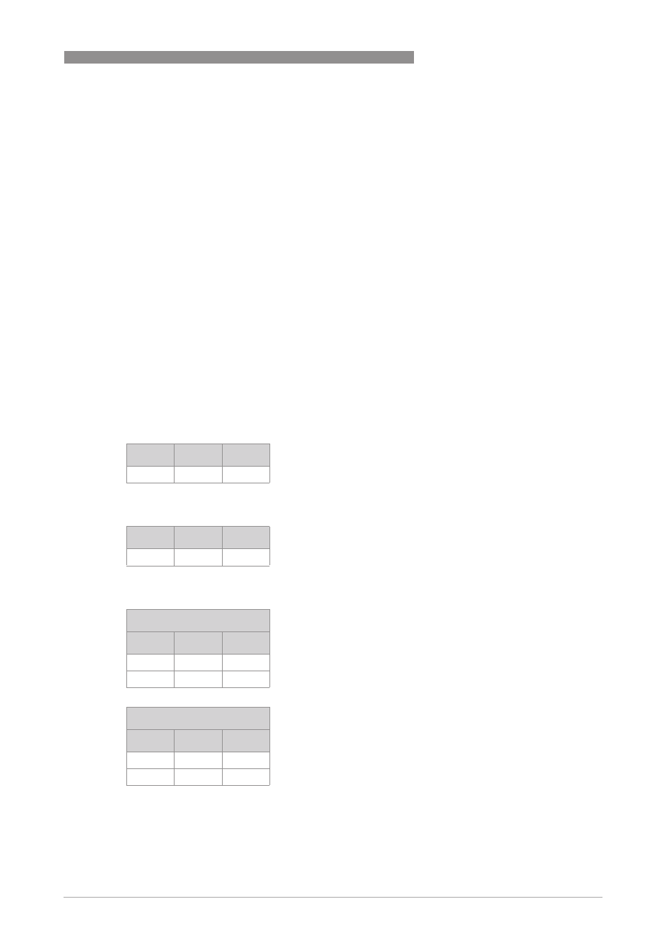
5.2.1 8-bit values
5.2.2 16-bit values
5.2.3 32-bit values
Register Hi
Lo
N
0x00
Byte
Register Hi
Lo
N
MSB
LSB
Little Endian
Register Hi
Lo
N
LSB + 1
LSB
N + 1
MSB
LSB + 2
Big Endian
Register Hi
Lo
N
MSB
LSB + 2
N + 1
LSB + 1
LSB