KROHNE ALTOSONIC III EN User Manual
Page 12
ALTOSONIC
III
12
3.6 Electrical
connection of
the signal
inputs and
outputs
The terminal to connect the electrical signal inputs
and outputs consist of 6 connections. For wiring of
the signal inputs and outputs it is advised to use
unshielded twisted pairs.
Terminal
Function
Specification
⊥
Common ground
-
P1
Pulse output 1, passive open collector output. Pulse
output to flow computer for volume counting.
Function can be set via menu option.
I
max
: 150 mA
U
max
: 32V DC, 24V AC
Max frequency: 1,5 kHz
P2
Pulse output 2, passive open collector output. 90° or
180° phase shifted from P1. For pulse fidelity checking
P1 and P2 should be connected to 2 separate inputs of
a flow computer.
Function can be set via menu option.
I
max
: 150 mA
U
max
: 32V DC, 24V AC
Max frequency: 1,5 kHz
S
Status output. Function can be set via menu option
3.5.0.
I
max
: 150 mA
U
max
: 32V DC, 24V AC
I/C
Current output (I), 0(4) to 20 mA
Passive open collector current sink output. Digital input
(C)
Function can be set via menu option 3.4.0. and 3.6.0.
Current output (I): I ≤ 22 mA,
R
load
≤ 680 Ohm. U
max
= 15V DC.
Digital input (C): low = 0-5 V DC, high = 15-32 V DC.
Will be switched off when current output activated.
The electrical input and output signals can be connected in passive mode. Please observe instrument polarity:
current (I) is always flowing towards P1, P2, S, I/C, terminals (current sink).
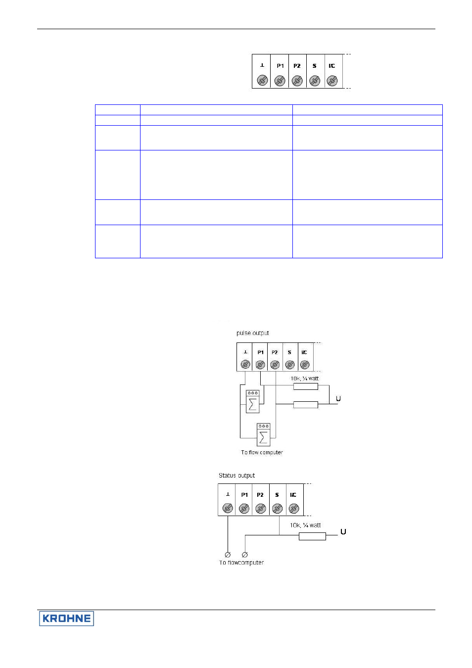
3.7 Connection
diagram
examples
Pulse output, P1,
P2
For supply:
U ≤ 32V DC, ≤
24V AC
Status output, S
For supply:
U ≤ 32V DC, ≤
24V AC