KROHNE VARIFLUX 6000 EN User Manual
Page 4
4
Installation instructions VARIFLUX 6000
1
Important information for installation: PLEASE NOTE !
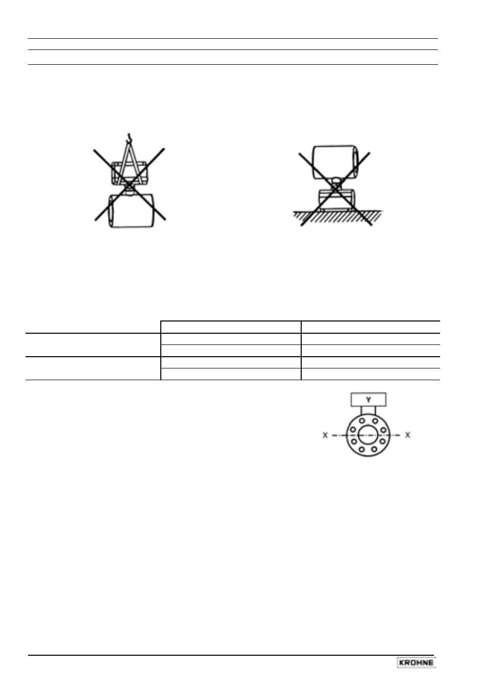
• Handling
Do not lift flowmeter by the signal converter
housing or the terminal box.
Do not set flowmeter down on signal converter
housing or terminal box.
PLEASE NOTE: the temperature limits for storage and transport, see below.
• Use only solventless detergents to clean the signal converter housing (polycarbonate).
• Temperatures
Refer to Section 11 “Limits” for operating pressure and vacuum load based on flange
standards and type of tube liner.
Ambient temperature
Process temperature
Compact systems
-25 to +60 °C (-13 to +140 °F)
-20 to + 60 °C (-4 to +140 °F)
-25 to +40 °C (-13 to +104 °F)
-20 to +140 °C (-4 to +284 °F)
VARIFLUX 6000
-25 to +60 °C (-13 to +140 °F)
-20 to + 60 °C (-4 to +140 °F)
-25 to +40 °C (-13 to +104 °F)
-20 to +140 °C (-4 to +284 °F)
• Location and position as required,
but electrode axis
X – • – • – • – X
must be approximately horizontal in a horizontal pipe run.
Y terminal box or converter housing
• Measuring tube must be completely filled at all times.
• Direction of flow is arbitrary. Arrow on flowmeter can normally be ignored. For exceptions,
refer to Section “Factory settings” in the installation and operating instructions for the signal
converter.
• Stud bolts and nuts: to fit, make sure there is sufficient room next to the pipe flanges.
• Vibration: support the pipeline on both sides of the compact flowmeter.
Level of vibration in conformity with IEC 068-2-34: 20-500 Hz, random / 2g runs / 30 minutes /
x, y, z directions.
• Do not expose to direct sunlight, fit a sunshade if necessary, not included with flowmeter,
to be provided by customer.