KROHNE PROFIFLUX IFS 5000 EN User Manual
Page 3
3
Items included with supply
IFS 5000 F
primary head
•
primary head
in the size as ordered
•
certificate of calibration data
•
installation material as specified
in the following table
•
installation instructions
IFM 5010 K, IFM 5020 K and IFM 5080 K
compact flowmeters
•
compact flowmeter
in the size as ordered
•
certificate of calibration data
•
installation material as specified
in the following table
•
installation instructions
•
installation and operating instruc-
tions for the signal converter
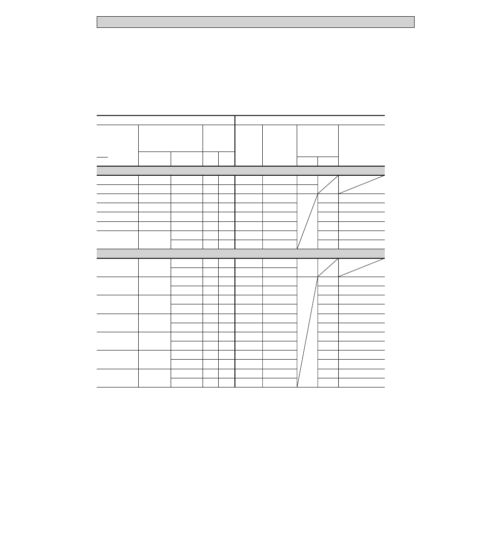
Flowmeter
Scope of supply ...
X = Standard
O = Option
Size of
measuring
tube
to ...
Pipe flanges
Meter sizes
Pressure rating
flange class
max. allowable
operating
pressure
1)
bar psig
... with
centering
material
... with
stud bolts
... with 2)
grounding
rings E and
gaskets ...
D1 D1+D2
... without 2)
grounding
rings but with
gaskets D3
and wires V
... DIN 2501 (BS 4504)
... ANSI B 16.5
DN
00
2.5 – 10
DN
0
15
DN
0
25
DN
0
40
DN
0
50
DN
0
80
DN 100
000
DN
0
10, 15
DN
0
15
DN
0
25
DN
0
40
DN
0
50
DN
0
80
DN 100
PN 40
PN 40
PN 40
PN 40
PN 40
PN 40
PN 16
PN 25
≤
40
≤
40
≤
40
≤
40
≤
40
≤
40
≤
16
≤
25
2
x
ring
2
x
ring
2
x
ring
4
x
sleeve
4
x
sleeve
6
x
sleeve
6
x
sleeve
6
x
sleeve
4
x
M12
4
x
M12
4
x
M12
4
x
M16
4
x
M16
8
x
M16
8
x
M16
8
x
M20
X
X
O
O
O
O
O
O
X
X
X
X
X
X
X
X
O
O
O
O
O
O
O
O
O
O
O
O
X
X
X
X
X
X
X
X
X
X
X
X
2
x
ring
2
x
ring
4
x
sleeve
2
x
ring
4
x
sleeve
4
x
sleeve
4
x
sleeve
4
x
sleeve
4
x
sleeve
6
x
sleeve
4
x
sleeve
6
x
sleeve
6
x
sleeve
6
x
sleeve
4
x 1
/
2
”
4
x 1
/
2
”
4
x 1
/
2
”
4
x 1
/
2
”
4
x 1
/
2
”
4
x 5
/
8
”
4
x 1
/
2
”
4
x 3
/
4
”
4
x 5
/
8
”
8
x 5
/
8
”
4
x 5
/
8
”
8
x 3
/
4
”
8
x 5
/
8
”
8
x 3
/
4
”
≤
20
≤
40
≤
20
≤
40
≤
20
≤
40
≤
20
≤
40
≤
20
≤
40
≤
20
≤
40
≤
20
≤
25
150 lb
300 lb
150 lb
300 lb
150 lb
300 lb
150 lb
300 lb
150 lb
300 lb
150 lb
300 lb
150 lb
300 lb
1
/
2
”
1
/
2
”
1”
1
1
/
2
”
2”
3”
4”
1
/
10
”–
3
/
8
”
1
/
2
”
1”
1
1
/
2
”
2”
3”
4”
1) For ANSI pipe flanges the max. allowable operating pressure is dependent on the process temperature,
see Sect. 10 “Technical data”.
2) For arrangement of gaskets and connection of wires V, see Section 7 “Grounding”.
≤
580
≤
580
≤
580
≤
580
≤
580
≤
580
≤
230
≤
360
≤
290
≤
580
≤
290
≤
580
≤
290
≤
580
≤
290
≤
580
≤
290
≤
580
≤
290
≤
580
≤
290
≤
360