KROHNE PROFIFLUX IFS 5000 EN User Manual
Page 10
10
8 Replacement of the separate primary head
Switch off power source before commencing work!
1) Note down terminal assignment before dismantling the “old“ primary head.
2) Install the new primary head as described in the supplied installation instructions.
3) Make electrical connection at the signal converter as described in the installation and
operating instructions for the signal converter.
4) Specific calibration data are defined during factory calibration for each primary head,
which are indicated on the instrument nameplate.
This includes the primary constant GK and the magnetic field frequency. These data
need to be reset in the signal converter.
5) If the size of primary head is also different from the old one, the full-scale range Q
100%
and
the meter size will need to be reset.
6) After resetting the signal converter, carry out a zero point check.
7) If necessary, reset the internal electronic totalizer of the signal converter.
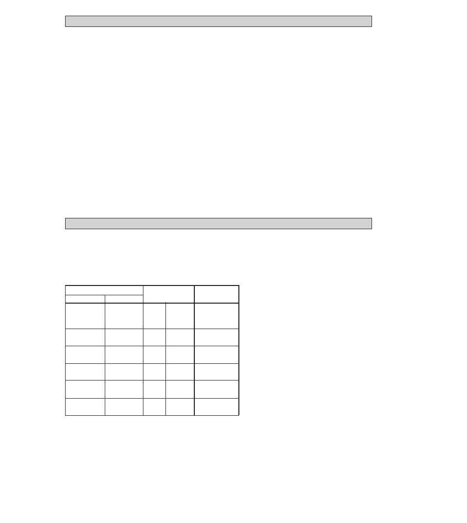
9 Spare parts and order numbers
Order No.
5.30020.03
5.30020.04
5.30023.02
5.30823.06
5.30823.01
5.30823.07
5.30823.02
5.30823.08
5.30823.03
5.30823.09
5.30823.04
5.30823.10
5.30823.05
Version,
material
Meter size
mm
inch
2.5 - 15
1
/
10
-
1
/
2
25
1
40
1
1
/
2
50
2
80
3
100
4
O
F
F
F
F
F
Viton
EPDM
Kalrez
G
C
G
C
G
C
G
C
G
C
Gaskets D1:
O = O-rings
F = flat rings
Material:
G = Gylon 3500
C = Chemotherm (graphite)
(Gasket arrangement, see Sect. 7)