Installation – KROHNE OPTITEMP TCA Ex EN User Manual
Page 24
3
INSTALLATION
24
OPTITEMP TRA/TCA
www.krohne.com
10/2010 - 4001087001 - Ex AD OPTITEMP TRA/TCA R02 en
If the process conditions at your measuring point are outside of the values in the tables used in
the example above, you will have to use charts. These can be found in the subchapters below
following the tables. The charts also include less common temperatures.
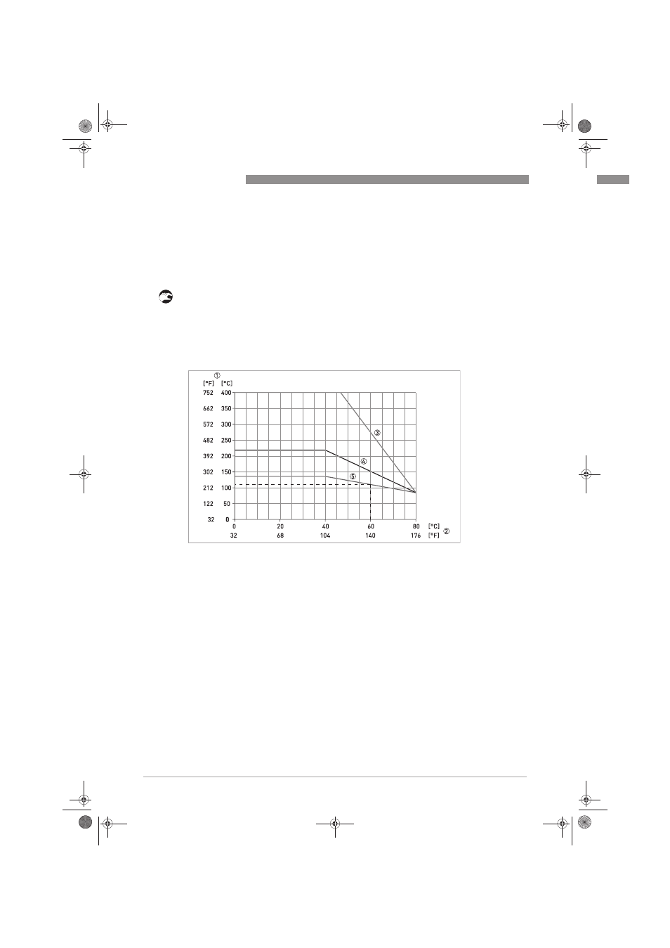
The following sample chart shows you how to calculate the temperature at the process
connection at an ambient temperature T
a
= 60°C / 140°F:
• Find the ambient temperature at your measuring point along the X-axis (in this case: 60°C /
140°F).
• From this point trace straight up until you reach the temperature curve of your thermometer.
• From this intersection, move horizontally to the left until you reach the Y-axis.
• At the intersection with the Y-axis read off the temperature at the process connection (in this
case: 108°C / 226°F).
Example: Calculating the temperature at the process connection (T
a
= 85°C / 185°F)
1 Maximum permitted temperature at process connection ( T
p
)
2 Ambient temperature at the measuring point (T
a
)
3 TxA-P14, insert thermometer without thermowell; TxA-P10, insert thermometer with thermowell; TxA-S12/41,
threaded thermometer; TxA-F13/42, flange thermometer; neck pipe length in each case ≥ 80 mm / 3.15"
4 TxA-P14, insert thermometer without thermowell; TxA-P10, insert thermometer with thermowell; neck pipe length in
each case ≤ 80 mm / 3.15"
5 TxA-S11, threaded thermometer, neck pipe length ≤ 80 mm / 3.15"
.book Page 24 Friday, November 19, 2010 2:23 PM