3 board layout, 4 system requirements, Led indicators – Asus ASMB-LE User Manual
Page 13
A S U S S e r v e r M a n a g e m e n t B o a r d ( A S M B - L E )
A S U S S e r v e r M a n a g e m e n t B o a r d ( A S M B - L E )
A S U S S e r v e r M a n a g e m e n t B o a r d ( A S M B - L E )
A S U S S e r v e r M a n a g e m e n t B o a r d ( A S M B - L E )
A S U S S e r v e r M a n a g e m e n t B o a r d ( A S M B - L E )
1 - 3
1 - 3
1 - 3
1 - 3
1 - 3
1.3
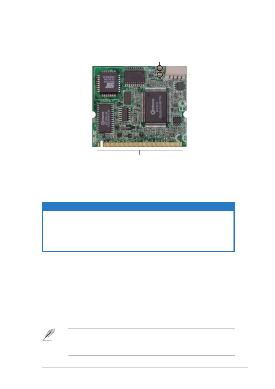
Board layout
The ASUS ASMB-LE comes in a BMC package. The illustration below shows
the major components of the server management board.
LED indicators
LED indicators
LED indicators
LED indicators
LED indicators
The ASMB-LE board comes with two LED indicators: BMC heartbeat LED
and Power LED. Refer to the table below for the LED indications.
1.4
System requirements
Before you install the ASMB-LE board, check if your server system meets
the following requirements:
•
ASUS server motherboard with Baseboard Management Controller
(BMC) socket*
•
LAN (RJ-45) port for server management**
•
Microsoft
®
Internet Explorer 5.5 or later
*
Visit the ASUS website (www.asus.com) for an updated list of server
motherboards that support the ASMB-LE board.
** Refer to the Appendix section for details.
L E D
L E D
L E D
L E D
L E D
N a m e
N a m e
N a m e
N a m e
N a m e
S t a t u s
S t a t u s
S t a t u s
S t a t u s
S t a t u s
D e s c r i p t i o n
D e s c r i p t i o n
D e s c r i p t i o n
D e s c r i p t i o n
D e s c r i p t i o n
L E D 1
L E D 1
L E D 1
L E D 1
L E D 1
B M C
B M C
B M C
B M C
B M C
Blinking
ASMB-LE firmware is in execution.
H e a r t b e a t
H e a r t b e a t
H e a r t b e a t
H e a r t b e a t
H e a r t b e a t
Off
The ASMB-LE firmware is corrupted or the
server system standby-power is off.
L E D 2
L E D 2
L E D 2
L E D 2
L E D 2
P o w e r
P o w e r
P o w e r
P o w e r
P o w e r
On
The managed server system is on.
Off
The managed server system is off.
S e r v e r
S e r v e r
S e r v e r
S e r v e r
S e r v e r
m a n a g e m e n t
m a n a g e m e n t
m a n a g e m e n t
m a n a g e m e n t
m a n a g e m e n t
c h i p
c h i p
c h i p
c h i p
c h i p
B o a r d c o n n e c t o r s
B o a r d c o n n e c t o r s
B o a r d c o n n e c t o r s
B o a r d c o n n e c t o r s
B o a r d c o n n e c t o r s
F i r m w a r e c h i p
F i r m w a r e c h i p
F i r m w a r e c h i p
F i r m w a r e c h i p
F i r m w a r e c h i p
P o w e r L E D
P o w e r L E D
P o w e r L E D
P o w e r L E D
P o w e r L E D
B M C h e a r t b e a t L E D
B M C h e a r t b e a t L E D
B M C h e a r t b e a t L E D
B M C h e a r t b e a t L E D
B M C h e a r t b e a t L E D
* Connects to an
IPMB connector on
the motherboard,
when available.