KEPCO RMW 300W Series Quick Start Guide User Manual
Open frame, Kepco, 300w, pfc, open frame power supplies
©2010, KEPCO, INC
1
Data subject to change without notice
228-1690
KEPCO, INC. 131-38 SANFORD AVENUE FLUSHING, NY. 11355 U.S.A. TEL (718) 461-7000 FAX (718) 767-1102
http://www.kepcopower.com email: [email protected]
Q U I C K S T A R T G U I D E
KEPCO
An ISO 9001 Company.
RMW
Open Frame
300W, PFC, OPEN FRAME
POWER SUPPLIES
I — INTRODUCTION
SCOPE OF MANUAL.
This Quick Start Guide covers
the installation and operation of the Kepco RMW
Series of Open Frame Switching Power Supplies. Full
specifications are listed in the Operator Manual that
can be downloaded from the Kepco web site:
• www.kepcopower.com/support/opmanls.htm#rmw
DESCRIPTION. Kepco RMW Series are 300W RoHS-
compliant switching power supplies with seven models pro-
viding 5V, 12V, 15V, 24V, 28V, 48V and a triple output
model (RMW 51212-300K) which provides a primary output
of +5V and secondary outputs of ±12V). All models also
include a separate +12V output that can be used to power
an external cooling fan and an output suitable for driving an
LED. Power Factor Correction (PFC) is included in all mod-
els.
Units may be operated with a nominal 115V a-c or 230V a-c
(input voltage range 85 to 264 Va-c), 50-60 Hz (input fre-
quency range 47-66Hz). If overvoltage protection trips, the
unit shuts down; it is necessary to cycle input power off,
then on to reset the unit. Overcurrent protection with auto-
matic recovery from short circuit is featured (except for sin-
gle-and triple output 5V models that latch off when
overcurrent or short-circuit is detected). Units are convec-
tion cooled U-chassis construction.
II — INSTALLATION
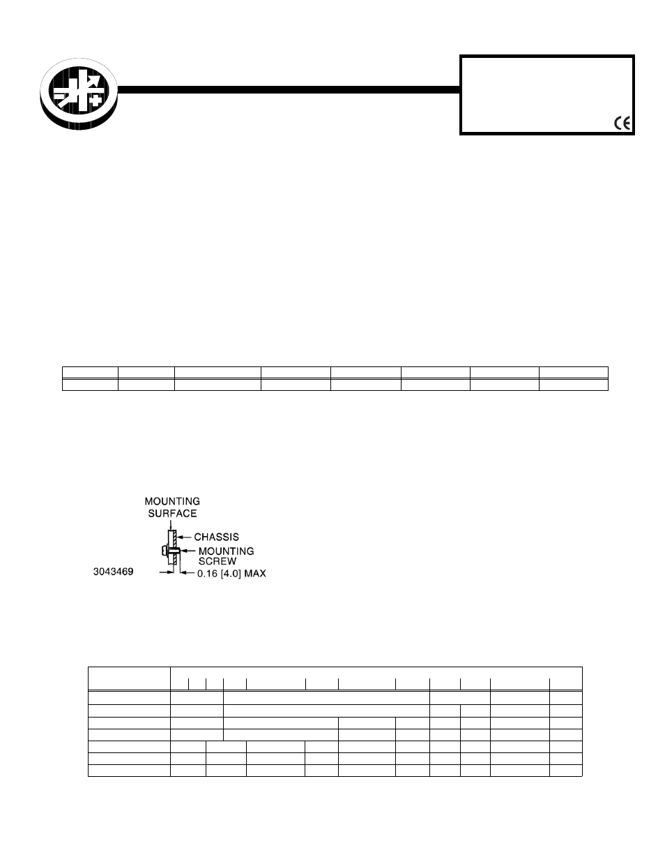
MOUNTING THE POWER SUPPLY. Refer to Figure
1. The unit may be mounted using 6-32 mounting screws
(not supplied). Eight mounting holes are provided: four on
the base, and two on each side. Note the restrictions for
maximum penetration of mounting screws (see Figure 1). .
FIGURE 1. MOUNTING SCREW PENETRATION
CONNECTIONS. All connections are made via TB1
through TB5 (see Figure 2 for locations). AC input power is
applied via the terminal block TB1. Connect the AC input
Neutral, Line and Earth Ground wires to the respective ter-
minals of the terminal block (see Figure 2). TB2 provides
the DC outputs; see Table 1 for pin allocation. TB3, TB4
and TB5 are each 2-pin connectors that require a Molex
5045-02A (or equivalent) mating connector. TB3 provides a
floating +12V output for use with an auxiliary fan (not sup-
plied). TB4 provides ± connections used for remote sens-
ing. TB5 provides connections used to drive an external
Power OK LED (not supplied).
Figure 3 shows proper connection of one or more loads. If
oscillations set off overvoltage protection, install one elec-
trolytic capacitor (470
µF min) between +S and + and one
between – and –S terminals.
TABLE 1. RMW OPEN FRAME MODELS
VOLTAGE
5V
5V, ±12V
12V
15V
24V
28V
48V
MODEL
RMW 5-60K
RMW 51212K-300
RMW 12-25K
RMW 15-20K
RMW 24-12K
RMW 28-11K
RMW 48-6.2K
TABLE 1. TB2 DC OUTPUT PIN ALLOCATION
OUTPUT TERMINAL
MODEL
1
2
3
4
5
6
7
8
9
10
11
12
RMW 5-60K
+5V
(1)
GND
+5V
RTN (+12V)
+12V
RMK 51212K-300
+5V
GND
+12V
–12V
---
---
RMW 12-25K
+12V
GND
RTN (+12V)
+12V
---
---
---
---
RMW 15-20K
+15V
GND
RTN (+12V)
+12V
---
---
---
---
RMW 24-12K
+24V
GND
RTN (+12V)
+12V
---
---
---
---
---
--
RMW 28-11K
+28V
GND
RTN (+12V)
+12V
---
---
---
---
---
--
RMW 48-6.2K
+48V
GND
RTN (+12V)
+12V
---
---
---
---
---
--
(1) CAUTION: Limit RMW 5-60K to 15A maximum per output terminal to avoid overheating