Ii — features, Iii — specifications, Input – KEPCO RKW 30W Series Operator Manual User Manual
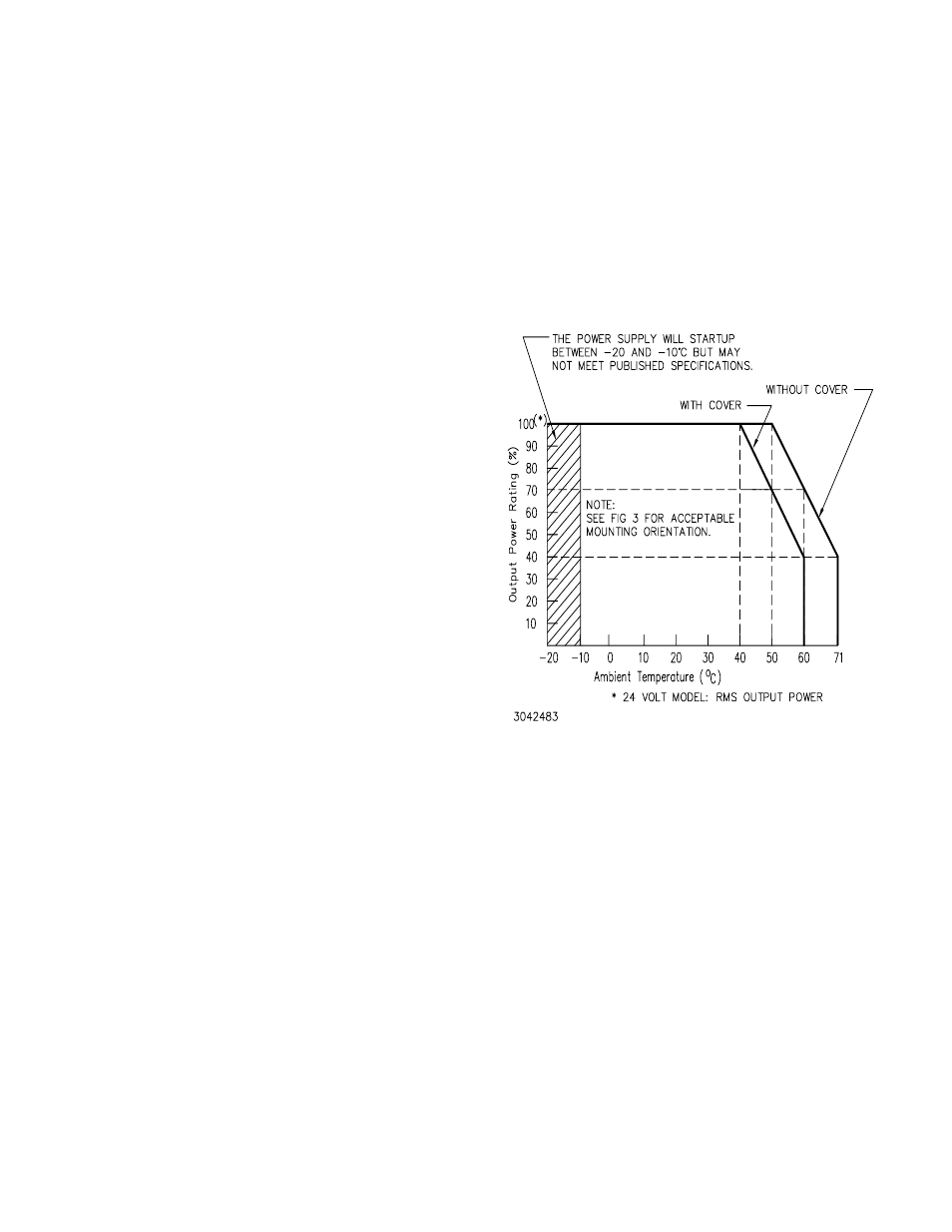
Page 2: Leakage current, Stabilization, Figure 1. output power vs. temperature, Transient recovery, Output holding time, Start up time, Overvoltage protection
2
228-1449 REV 5
082610
KEPCO, INC. 131-38 SANFORD AVENUE FLUSHING, NY. 11355 U.S.A. TEL (718) 461-7000 FAX (718) 767-1102
http://www.kepcopower.com email: [email protected]
II — FEATURES
• Green Output on LED indicator
• Overvoltage/Overcurrent protection
• Power Factor Corrected, wide range a-c input
• Convection cooling
• SEMI-47 compliant
• RoHS compliant
• DIN-Rail mountable
• Series Operation
III — SPECIFICATIONS
The following specifications are at nominal input voltages
at 25°C unless otherwise specified.
INPUT:
Voltage: 100-240V a-c nominal; Range 85-265V a-c
(0 to 100% load, -10 to 71°C); 110-370V d-c.
(polarity insensitive; consult factory) Safety
agency approval applies only to a-c input opera-
tion.
Frequency: Nominal 50-60 Hz; Range 47-440Hz (0
to 100% load, -10 to 71°C), (at 440Hz leakage cur-
rent exceeds UL/VDE safety specification limit).
Current (nominal output at 100% load):
@100-120V a-c rms:
5V-48V models: 0.85A a-c rms max. 0.65A typ.
3.3V model: 0.7A rms max., 0.55A typ.
@200-240V a-c rms:
5V-48V models: 0.45A a-c rms max. 0.38A typ.
3.3V model: 0.4A rms max., 0.33A typ.
Input Protection and Soft Start: Units are protected
against shorts by an input fuse. Fuse value 2A,
250V.
Initial Turn-on Surge: (cold start 25 °C, 100% load,
first surge only, not including the current flow into
the EMI filter):
@100V a-c rms: 12.5A typ.,
@200V a-c rms: 25A typ.
Switching Frequency: 60kHz typical (flyback) nomi-
nal load
LEAKAGE CURRENT:
@120V a-c and 60 Hz: 0.55mA max, 0.32mA typ.
@240V d-c and 60 Hz: 0.75mA max, 0.50mA typ.
(operating in conformance with UL 1950/IEC 950)
STABILIZATION:
Source Effect (Range 85 to 132Va-c or
170-265 Va-c):
5V to 48V Models: 0.1% typ., 0.2% max.
3.3V Model: 5mV typ., 10mV max.
Load Effect, measured at sensing terminals
(0% - 100% of rated output current):
5V to 48V Models: 0.3% typ., 0.6% max;
3.3V Model: 15mV typ., 30mV max.
Temperature effect: (-10 to 71°C)
0.5% typ., 1.0% max.
Combined effect: 0.9% typ., 1.8% max.
Drift: (1/2 to 8 hr. at 25°C) 0.2% typ., 0.5% max.
FIGURE 1. OUTPUT POWER VS. TEMPERATURE
TRANSIENT RECOVERY: A step load change from
50% to 100% of rated output current in 50 microseconds
or more, produces no more than 4% output voltage excur-
sion (3.3V model: ±200mV max.). Recovery time is 1ms
maximum.
OUTPUT HOLDING TIME: Upon input interruption
the output is maintained for:
@100V a-c: 35 mS typ. (20 mS min.)
@240V a-c: 230 mS typ. (130mS min.).
START UP TIME:
@100V a-c: 900mS max., 600mS typ.
@240V a-c: 400mS max., 200mS typ.
OVERVOLTAGE PROTECTION: Fixed, factory set.
See Table 1. The overvoltage circuit is set by Zener diode
clamp, latching will occur.