Iii — operation, Remote on-off control, Remote voltage programming – KEPCO RKE 1500W Series Quick Start Guide User Manual
Page 2: Parallel or series operation, Preliminary electrical check, Protection and alarms
2
228-1707 REV 2
082312
KEPCO, INC. 131-38 SANFORD AVENUE FLUSHING, NY. 11355 U.S.A. TEL (718) 461-7000 FAX (718) 767-1102
http://www.kepcopower.com email: [email protected]
III — OPERATION
When output voltage is available, the green LED is on.
The Output Voltage Adjust trimmer (see Figure 3) allows
adjustment of the output voltage.
REMOTE ON-OFF CONTROL When remote ON/
OFF is not in use, ±RC terminals must be shorted (use
shorting link supplied) for unit to operate. Remove short
across ±RC and apply “high,” 2.4V to 24V (or open),
across ±RC to turn output voltage OFF. Apply “low,” 0.0V
to 0.4V (or short) across ±RC to turn output voltage ON.
Source current is 1.6mA maximum for low level logic, and
sink current is 1.0 mA maximum at high level. The ±RC
terminals are isolated from the a-c input terminal and the
DC output terminals.
REMOTE VOLTAGE PROGRAMMING In addition
to the integral trimmer, output voltage can also be
adjusted via an external variable resistance or external
variable d-c voltage. Refer to the Operator’s Manual for
details.
PARALLEL OR SERIES OPERATION Power Sup-
plies can be connected in parallel (with or without N+1
redundancy) for increased current or in series for
increased voltage. Refer to Operator’s Manual for details.
PRELIMINARY ELECTRICAL CHECK To verify
power supply functionality, refer to Operator Manual for
details.
PROTECTION AND ALARMS Refer to Operator
manual for details regarding overvoltage, overtempera-
ture, current limit/overcurrent, fan failure and undervoltage
protection and the Power Fail alarm signal.
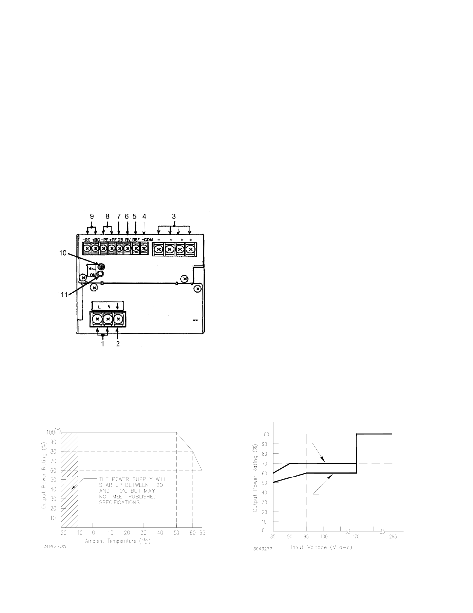
FIGURE 3. CONTROLS, INDICATORS AND TERMINAL LOCATIONS
FIGURE 4. POWER RATING VS. TEMPERATURE AND INPUT VOLTAGE
LEGEND:
1. AC input terminals (L, N): Connect to AC, 100 to 240V, input line.
2. Frame Ground (earth) terminal: Connect to earth ground. This termi-
nal is connected to the case.
3. DC output terminals (+, -): Connect to load (see Figure 2).
4. Signal Common (-COM): Provides return for REF and RV signals
5. Reference Voltage (REF): Using the REF terminal (together with the
RV terminal), all the output voltages of slave power supplies can be
controlled by one voltage adjustment of a master power supply (nor-
mally it is shorted with a metal shorting link to the RV terminal).
6. Output Voltage Adjust (RV): This terminal (together with the REF ter-
minal) is used for remotely controlling output voltage.
7. Current Balance (CB): This terminal is used when several power sup-
plies are connected in parallel.
8. Power failure (+PF, -PF): These terminals output an open logic signal
if output voltage drops to 80% or lower of a set voltage (5V or lower for
36V model), or if output voltage is shut down due to overvoltage or cur-
rent limit protection, fan speed failure, or overheating.
9. Remote ON-OFF (+RC, -RC): Output is turned ON-OFF by opening-
shorting the RC terminals (output OFF when open). RC terminals are
isolated from input and output terminals. Normally, ±RC terminals are
shorted with a metal shorting link.
10. Output voltage adjustment trimmer (V.ADJ): Adjusts output voltage.
11. Output ON indicator: This green LED lights when output voltage is more than 80% of the programmed voltage.
NOTE Unit is shipped with shorting link)s (not shown)
connecting +RC to –RC and REF to RV.
POWER RATING VS. TEMPERATURE
36 V MODEL
48 V MODEL
24V MODEL
POWER RATING VS. INPUT VOLTAGE