KEPCO RKE 1500W Series Quick Start Guide User Manual
Kepco, Single output 1500w power supplies
©2012, KEPCO, INC
1
Data subject to change without notice
228-1707 REV 2
KEPCO, INC. 131-38 SANFORD AVENUE FLUSHING, NY. 11355 U.S.A. TEL (718) 461-7000 FAX (718) 767-1102
http://www.kepcopower.com email: [email protected]
Q U I C K S T A R T G U I D E
KEPCO
An ISO 9001 Company.
RKE
SINGLE OUTPUT
1500W POWER SUPPLIES
I — INTRODUCTION
SCOPE OF MANUAL. This Quick Start Guide covers
the installation and operation of the Kepco RKE 1500W
Series of PFC (Power Factor Corrected), RoHS (Reduction
of Hazardous Substances) compliant, programmable
switching power supplies. Full specifications are listed in
the applicable Operator’s Manual that can be downloaded
from the Kepco web site:
• www.kepcopower.com/support/opmanls.htm#rke
DESCRIPTION. The Kepco RKE 1500W Series con-
sists of three models of switching power supplies, each with
a single output of 24V, 36V or 48V as shown in Table 1.
Units may be operated with a nominal 100V a-c to 240V a-
c (input voltage range 85 to 265 Va-c), 50-60 Hz (input fre-
quency range 47-66Hz). Overvoltage protection and an iso-
lated remote TTL ON-OFF control are provided. An LED
“output voltage ON” light and an output voltage adjust trim-
mer are visible below the control terminals (left side of the
case). Units are manufactured on a steel frame with a steel
cover.
II — INSTALLATION
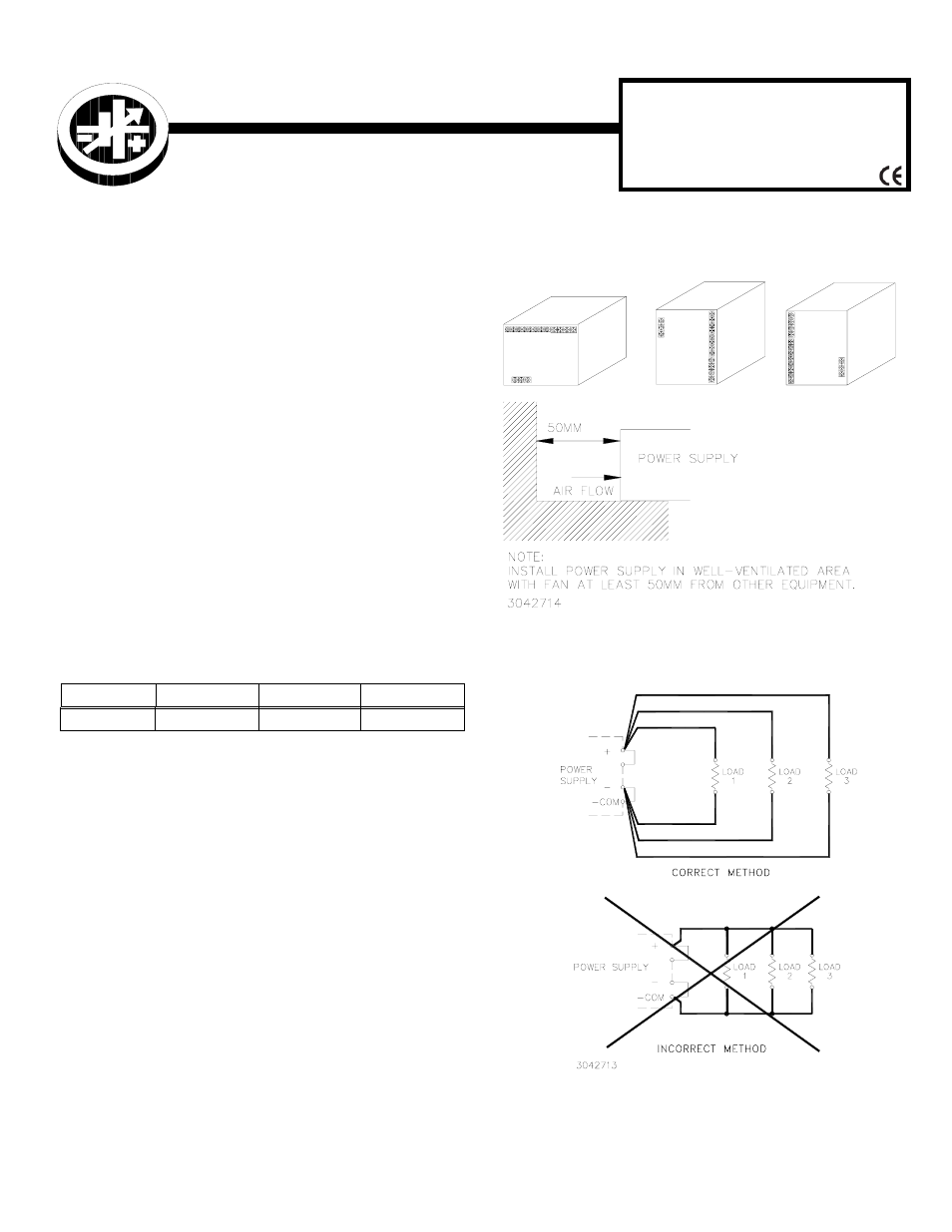
MOUNTING THE POWER SUPPLY: The unit may
be mounted on one mounting surface as shown in Figure 1.
Maximum penetration of mounting screws (M4) is 0.24 in (6
mm) from case. The air surrounding the power supply must
not exceed the ambient temperature values given in the
graph in Figure 4.
CONNECTIONS: Figure 2 shows proper connection of
one or more loads. AC input power is applied via the termi-
nal block (see Figure 3). Make sure to connect the AC input
Neutral, Line and Ground wires to the respective terminals
of the terminal block,
FIGURE 1. POWER SUPPLY MOUNTING DIRECTION
FIGURE 2. LOAD CONNECTIONS
TABLE 1. RKE MODELS
MODELS
24V
36V
48V
1500W
RKE 24-50K
RKE 36-42K
RKE 48-32K
Document Outline
- I — INTRODUCTION
- SCOPE OF MANUAL.
- DESCRIPTION.
- TABLE 1. RKE Models
- II — INSTALLATION
- Mounting the Power Supply:
- Connections:
- FIGURE 1. Power Supply Mounting Direction
- FIGURE 2. Load Connections
- III — OPERATION
- Remote On-Off Control
- Remote Voltage Programming
- Parallel or Series Operation
- Preliminary Electrical Check
- Protection and Alarms
- FIGURE 3. Controls, Indicators and Terminal Locations
- FIGURE 4. Power Rating Vs. Temperature and Input Voltage