KEPCO RA 19-8B Quick Start Guide User Manual
Page 5
KEPCO, INC. 131-38 SANFORD AVENUE FLUSHING, NY. 11355 U.S.A. TEL (718) 461-7000 FAX (718) 767-1102
http://www.kepcopower.com email: [email protected]
080309
228-1681
5
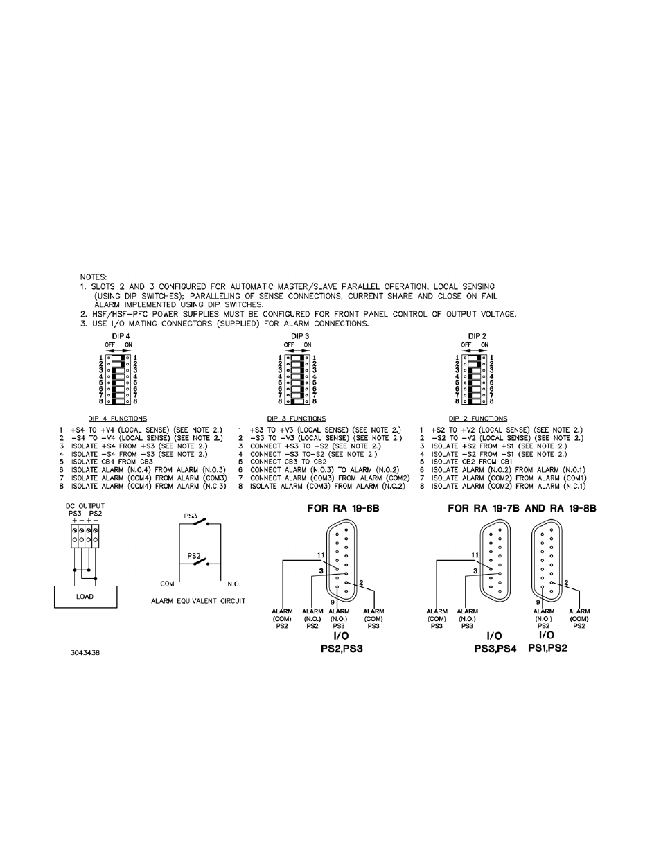
Configure DIP 2:
1. Set positions 1 and 2, to ON. This connects +S to +V
and –S to –V for slot 2, establishing local sensing for slot
2.
2. Set positions 3 and 4, to OFF. This isolates sense lines
(±S) between slots 2 and 1.
3. Set position 5 to OFF. This isolates the current share
bus (CB) between slots 2 and 1.
4. Set position 6 and 7, to OFF. This isolates the ALARM
(N.O.) and ALARM (COM) lines between slots 2 and 1.
5. Set position 8 to OFF. This position is only set to ON for
open-on-fail alarm circuits.
SERIES OPERATION. See RA 19-(X)B Operator
Manual for series operation details.
ALARMS. For independent configurations, Close on Fail
contact closure is across I/O connector pins for ALARM
N.O. and ALARM COM (see Figure 4). Open on Fail cir-
cuits are across I/O connector pins for ALARM N.C. and
ALARM COM. Figure 4 shows a parallel close-on-fail circuit
for slots 2 and 3 using the DIP switches to make the con-
nections. See Operator Manual for other options.
FIGURE 4. SLOTS 2 AND 3 CONFIGURED FOR PARALLEL OPERATION, WITH CLOSE ON FAIL ALARM CIRCUIT