KEPCO RA 19-8B Quick Start Guide User Manual
Page 4
4
228-1681
080309
KEPCO, INC. 131-38 SANFORD AVENUE FLUSHING, NY. 11355 U.S.A. TEL (718) 461-7000 FAX (718) 767-1102
http://www.kepcopower.com email: [email protected]
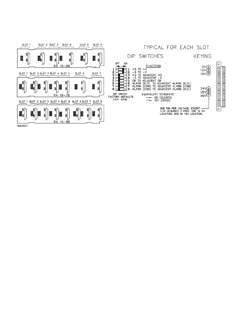
FIGURE 3. BACKPLATE, INTERIOR VIEW, DIP SWITCHES AND KEYING
PARALLEL OPERATION. The most common use for
the RA 19-(X)B rack adapter is with two or more HSF’s
connected in parallel to a single load with forced current
sharing to increase current output, increase reliability and/
or provide redundancy. Only adjacent slots can be con-
nected in parallel using DIP switches.
Figure 4 shows HSF’s in slots 2 and 3 connected in paral-
lel (master/slave, master established automatically by
voltage) with forced current sharing and a close-on-fail
alarm circuit. Both HSF modules are configured for output
voltage to be adjusted from the front panel trimpot (factory
default setting). See HSF operator manual for other output
voltage adjustment options.
Configure DIP 4:
1. Set positions 1 and 2, to ON. This connects +S to +V
and –S to –V for slot 4, establishing local sensing for
slot 4 if slot 4 is to be used.
2. Set positions 3 and 4, to OFF. This isolates sense lines
(±S) between slots 4 and 3.
3. Set position 5 to OFF. This isolates the current share
bus (CB) between slots 4 and 3.
4. Set position 6 and 7, to OFF. This isolates the ALARM
(N.O.) and ALARM (COM) lines between slots 4 and 3.
5. Set position 8 to OFF. This position is only set to ON for
open-on-fail alarm circuits.
Configure DIP 3:
6. Set positions 1 and 2, to ON. This connects +S to +V
and –S to –V for slot 3, establishing local sensing for
slot 3.
7. Set positions 3 and 4, to ON. This connects sense lines
(+S to +S and –S to –S) for slots 3 and 2.
8. Set position 5, to ON. This connects the current share
bus (CB) for slots 3 and 2.
9. Set positions 6 and 7 to ON. Position 6 connects the
normally open ALARM (N.O.) lines and position 7 con-
nects the ALARM (COM) (common) for slots 3 and 2,
implementing a close-on-fail alarm circuit (see equiva-
lent schematic shown in Figure 4. If either PS2 or PS3
fails, a contact closure provides continuity across pins 7
and 14 of both I/O 4 and I/O 3.
10.Set position 8 to OFF. This position is only set to ON
for open-on-fail alarm circuits.