Figure 2. mounting direction, Figure 3. ventilation and insulation requirements, S 2, 3 – KEPCO MTW 30 User Manual
Page 3
031908
228-1547 REV 3
3
KEPCO, INC. " 131-38 SANFORD AVENUE " FLUSHING, NY. 11355 U.S.A. " TEL (718) 461-7000 " FAX (718) 767-1102
http://www.kepcopower.com " email: [email protected]
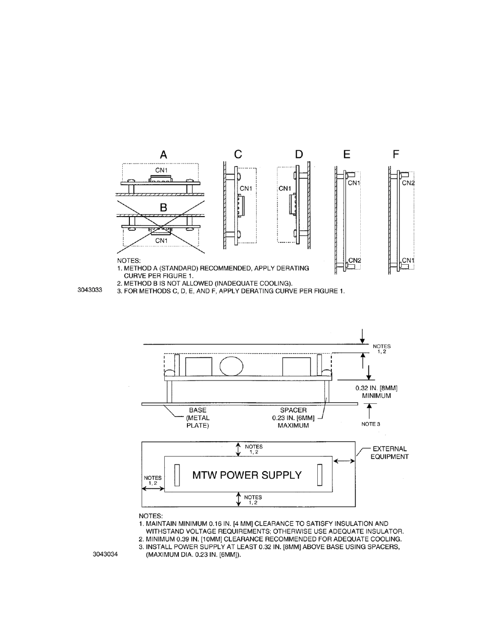
INSTALLATION (INSULATION):
Install unit 0.3 inches (8mm) away from base with the use of 0.24 inch (6mm) diameter spacers
attached to the PC board. Keep at least 0.16 inches (4mm) spacing around and above the unit to comply with insulation and safety require-
ments. An insulator must be used if the spacing is less than 0.16 inches (4mm) (see Figure 3).
VENTILATION:
It is recommended to keep at least 0.40 inches (10mm) clearance from adjacent equipment for proper ventilation
CONNECTIONS:
Connect a load to the +5V output of the power supply by connecting pin 6 of output connector CN2 (+5V) to the load (+)
terminal, and pin 5 (5V Return) to the load (–) terminal (see Figure 4 for input/output connector/pin locations). Connect a load to the +12V
output of the power supply by connecting pin 4 (+12V) of connector CN2 to the load (+) terminal, and pin 3 (±12V Return) to the load (–) ter-
minal. Connect a load to the -12V output of the power supply by connecting pin 1 (–12V) of connector CN2 to the load (–) terminal, and pin 2
(±12V Return) to the load (+) terminal.The AC input power is applied via input connector CN1. Make sure to connect the AC input Neutral
and Line wires to pins 3 and 1, respectively, of CN1 (see Figure 2). See Table 2 for mating connector information. A Cable Kit (P/N 219-0486)
is available as an option from Kepco. The kit includes an input cable, terminated on one end with an input mating connector; and an output
cable, terminated on one end with an output mating connector.
FIGURE 2. MOUNTING DIRECTION
FIGURE 3. VENTILATION AND INSULATION REQUIREMENTS