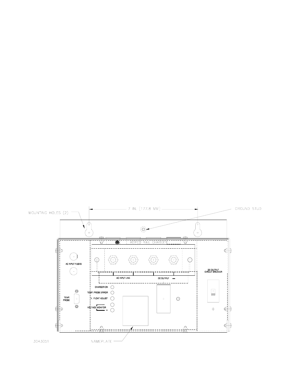
Figure 1. model krr 12-40, front view, Iv — operation – KEPCO KRR 12-40 Railroad Battery Charger User Manual
Page 4
4
228-1562
011906
KEPCO, INC. " 131-38 SANFORD AVENUE " FLUSHING, NY. 11352 U.S.A. " TEL (718) 461-7000 " FAX (718) 767-1102
http://www.kepcopower.com " email: [email protected]
IV — OPERATION
USING TEMPERATURE COMPENSATION FOR LEAD-ACID BATTERY (OPTIONAL)
Temperature compensation allows the output voltage of the Model KRR 12-40 battery charger to be automatically decreased
or increased for temperatures above or below 77°F (25°C), respectively. Compensation is 3mV/(°F)(cell) or 5.4mV/(°C)(cell),
so for a standard 12 Volt battery using six 2-volt cells, compensation is 18mV/°F. As an example, if temperature measured
by the sensor was 80°F, (3°F above 77°F) the output voltage would be decreased by 3 x 18mV = 54mV. Since the tempera-
ture is expected to rise while charging, and then fall as the battery becomes fully charged, temperature compensation can
prolong battery life by adjusting the float voltage automatically.
1.
Connect the temperature probe cable to the TEMP PROBE connector at the front panel. Verify that the TEMP PROBE
ERROR indicator is not lit.
2.
Attach the temperature probe to the negative (–) terminal of the battery being charged. If the threaded stud is long
enough, mount the probe on the threaded stud and attach with another nut. Otherwise, remove the existing nut and use
it to attach the temperature probe. In either case observe torque requirements when tightening the nut.
CHARGING THE BATTERY
1.
If the float voltage has been preset, proceed to step 2. Otherwise, refer to PRESETTING THE OUTPUT under INSTAL-
LATION and set the float voltage for the battery to be charged.
2.
Connect the battery (see INSTALLATION) and install temperature compensation if desired (see above). Verify all bat-
tery and a-c line connections are tight.
3.
Apply a-c source power to the unit. If the circuit breaker pops, the battery connections are reversed; disconnect a-c
power, reverse the battery connections, reapply a-c power and turn on the circuit breaker. The front panel ammeter indi-
cates the charging current. NOTE: If the CHARGER ON indicator fails to light, verify that a-c source power is present
and that the AC INPUT fuses have not blown.
4.
When the charging current as indicated on the front panel ammeter falls to near zero, the battery is fully charged.
FIGURE 1. MODEL KRR 12-40, FRONT VIEW
CURRENT
+
+
L
L
1
2
CURRENT