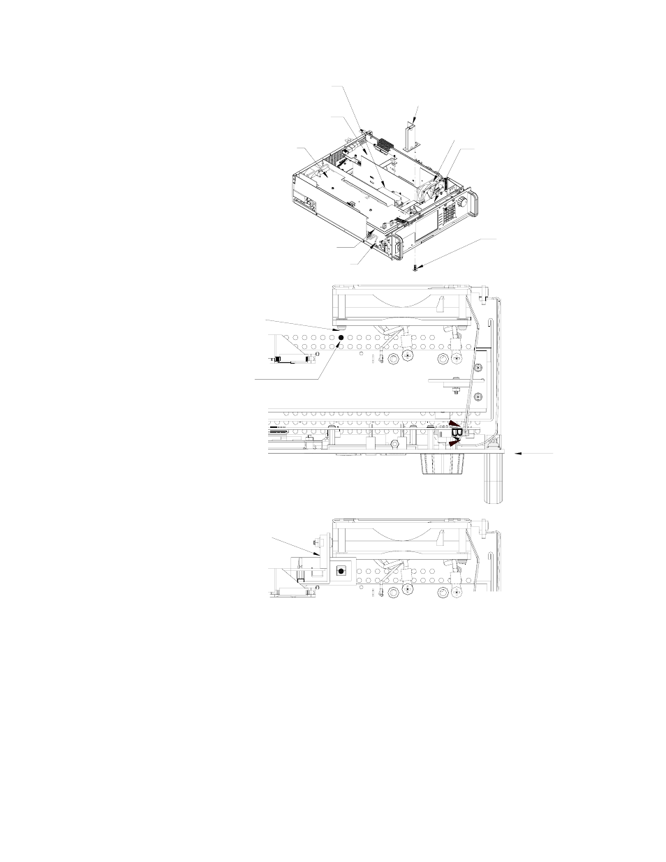
Figure 2. bop 1kw component locations, E 2 for – KEPCO Kit 219-0553, Transition Circuit Kit BOP 72-14MG User Manual
Page 3
071812
228-1749 REV 1
3
KEPCO, INC. 131-38 SANFORD AVENUE FLUSHING, NY. 11355 U.S.A. TEL (718) 461-7000 FAX (718) 767-1102
http://www.kepcopower.com email: [email protected]
FIGURE 2. BOP 1KW COMPONENT LOCATIONS
3. Install the 4-pin cable assembly (P/N 118-1266) on Transition Circuit A7A3J3 of the PCB (see Figure 1). Route
the cables as shown by Figure 6. This cable has three (3) unterminated wires. Determine the needed length,
cut the wire and remove the insulated sleeving (approximately 0.15"), then solder each wire to the indicated
point (see Figure 3 for A4A8 component locations and Figure 6 for cable routing):
• red wire to A4A8D1 Cathode
• black wire to A4A8D1 Anode
• white wire to A4A8TP2
A4A3 ASSEMBLY
(SEE FIGURE 6,)
A4A1 ASSEMBLY
A2A5 ASSEMBLY
(SEE FIGURE 5.)
OUTPUT MODULE
(A2) FAN)
A4A8 ASSEMBLY
(SEE FIGURE 4.)
AUXILIARY
POWER SUPPLY A5
CHASSIS GROUND CONNECTION
3043609
TRANSITION CIRCUIT
ASSEMBLY A7A3
(SEE DETAILS "A" AND "B")
SCREW, TPTH,
8-18 X 0.625 IN.
KEPCO P/N 101-0328
DETAIL "A"
(PARTIAL TOP VIEW)
A7A3 SCREW LOCATION
INSERT SCREW IN THIS
VENTILATION HOLE (IN LINE
WITH FAN MOUNTING SCREW)
TO MOUNT TRANSITION
CIRCUIT ASSEMBLY A7A3.
FAN MOUNTING
SCREW
FRONT
PANEL
DETAIL "B"
(PARTIAL TOP VIEW)
A7A3 INSTALLED
TRANSITION
CIRCUIT
A7A3
(See Note)
NOTE: For flush mounting of
chassis in rack,
contact Kepco