KEPCO Kit 219-0553, Transition Circuit Kit BOP 72-14MG User Manual
Page 2
2
228-1749 REV 1
071812
KEPCO, INC. 131-38 SANFORD AVENUE FLUSHING, NY. 11355 U.S.A. TEL (718) 461-7000 FAX (718) 767-1102
http://www.kepcopower.com email: [email protected]
3.2 COVER REMOVAL PROCEDURE
WARNING: Before installing the kit, unplug the BOP from a-c input source and disconnect the output
load!
1. Turn power off and disconnect the unit from source power and remove line cord, then disconnect the output
load.
NOTE: Retain all hardware for reassembly.
2. Remove the two mounting ears from the chassis by removing three screws from each.
CAUTION: The two screws at the top of the front panel must be removed first to avoid damage to the
front panel.
3. Remove the top cover of the unit by removing 14 screws as follows: two at top of the front panel, four at each
side, (one towards the rear, three at the bottom) and four at the top of the rear panel.
3.3 PRINTED CIRCUIT BOARD AND HEAT SINK INSTALLATION PROCEDURE
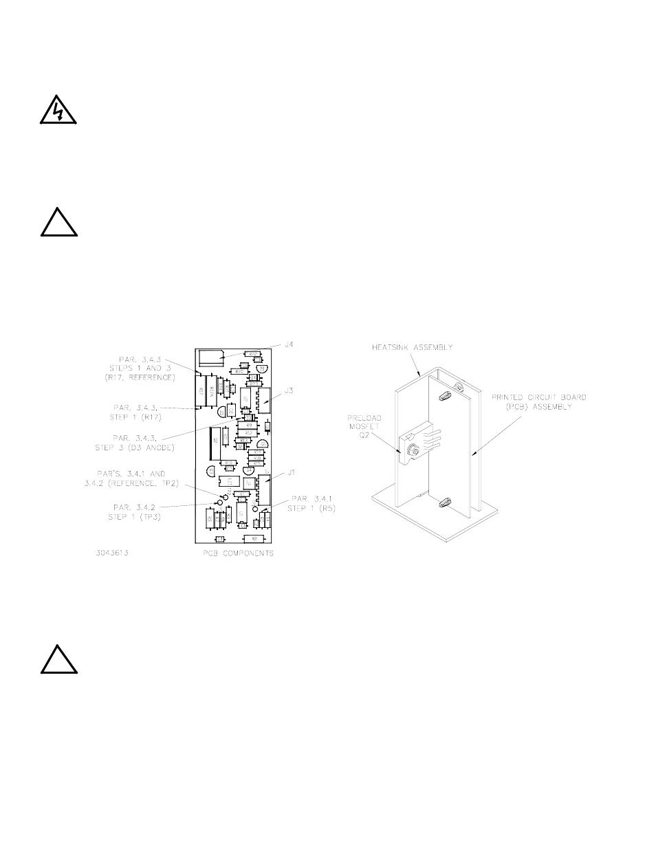
The Transition Circuit assembly Printed Circuit Board (PCB) is shipped assembled to the Heatsink with the pre-
load-MOSFET mounted directly on the heatsink (Figure 1).
FIGURE 1. TRANSITION CIRCUIT ASSEMBLY, COMPONENT LOCATIONS
1. Install the Transition Circuit assembly as shown in Figure 2 using the ventilation hole identified in the figure
and the screw provided in this kit. The screw is inserted up through the bottom of the chassis into the plastic
grommet of the heatsink. The plastic grommet keeps the Transition Circuit assembly electrically isolated from
the chassis.
CAUTION: When routing cables, ensure that the cables stay clear of the Output Module (A2) Fan and
Auxiliary Power Supply (A5).
2. Cable assembly P/N 118-1267 (provided in the Kit) has a 3-pin connector with two wires, each having non-iso-
lated ring lugs. Remove the screws and lockwashers from J4M and J2M on A4A8, then add the wires from the
cable assembly to the wires already connected to J4M and J2M as follows (see Figure 2 for the location of
A4A8 in the chassis, Figure 3 for location of J4M and J2M and Figure 6 for cable routing):
• red/white wire to A4A8- J4M
• black/white wire to A4A8- J2M
!
!