KEPCO Kit 219-0540, BOP 1000W Troubleshooting Kit User Manual
Kepco, Bop 1kw troubleshooting kit, Troubleshooting
©2008, KEPCO, INC
1
Data subject to change without notice
228-1669
I N S T R U C T I O N M A N U A L
BOP 1KW
KEPCO
KEPCO, INC. " 131-38 SANFORD AVENUE " FLUSHING, NY. 11355 U.S.A. " TEL (718) 461-7000 " FAX (718) 767-1102
http://www.kepcopower.com " email: [email protected]
An ISO 9001 Company.
TROUBLESHOOTING
KIT 219-0540
BOP 1KW
TROUBLESHOOTING KIT
1. DESCRIPTION
Kepco KIT 219-0540 contains two connector printed circuit board assemblies and one ribbon cable which allow the
A2 assembly of BOP 1000W power supply to be operated while physically removed from the chassis for trouble-
shooting purposes.
2. INSTALLATION INSTRUCTIONS
2.1 MATERIAL REQUIRED (SEE TABLE 1.)
2.2 REMOVAL PROCEDURES
1. Refer to applicable BOP 1000W Service Manual and remove the cover, then remove A1 assembly.
2. Refer to applicable BOP 1000W Service Manual and remove A2 assembly with U-shaped shroud from chassis,
then remove A2 assembly from shroud.
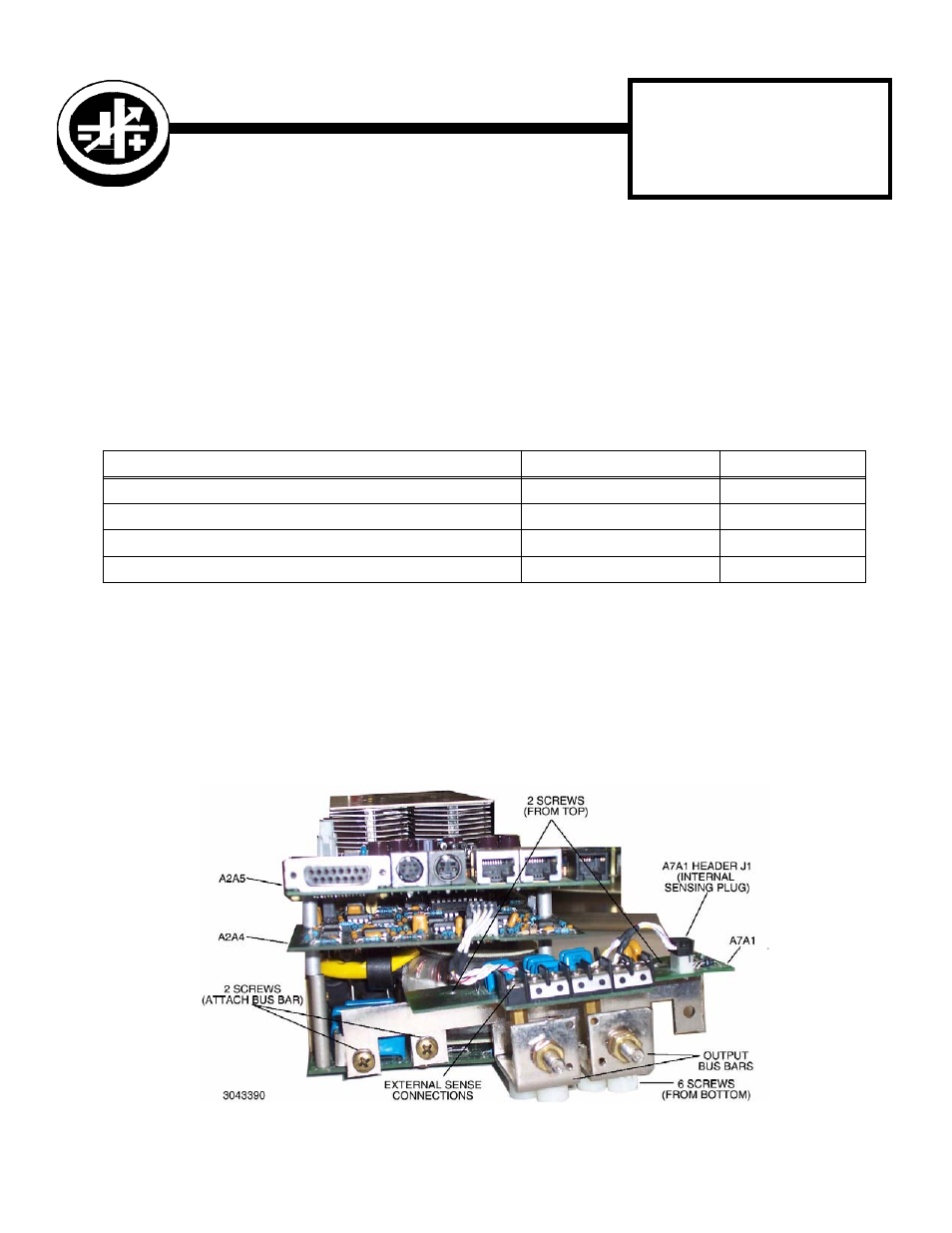
3. Disassemble bus bars together with A7A1 board by removing two screws from top and six screws from bottom
(see Figure 1).
4. Use two screws to attach bus bars with A7A1 to A2 assembly (see Figure 1) and connect the internal sensing
cable to header J1 of A7A1.
FIGURE 1. BUS BAR REMOVAL, REASSEMBLY
TABLE 1. MATERIAL REQUIRED
MATERIAL
LOCATION
QUANTITY
• Printed circuit board connector assembly Kepco P/N 236-2750)
Provided in this Kit
1
• Printed circuit board connector assembly Kepco P/N 236-2744)
Provided in this Kit
1
• Ribbon cable assembly (Kepco P/N 118-1217)
Provided in this Kit
1
• Instruction Manual 228-1669
Provided in this Kit
1