KEPCO Kit 219-0538, KLP Firmware Upgrade Kit (Version 7.xx to Version 8.xx) User Manual
Page 2
2
228-1653
042408
KEPCO, INC. " 131-38 SANFORD AVENUE " FLUSHING, NY. 11355 U.S.A. " TEL (718) 461-7000 " FAX (718) 767-1102
http://www.kepcopower.com " email: [email protected]
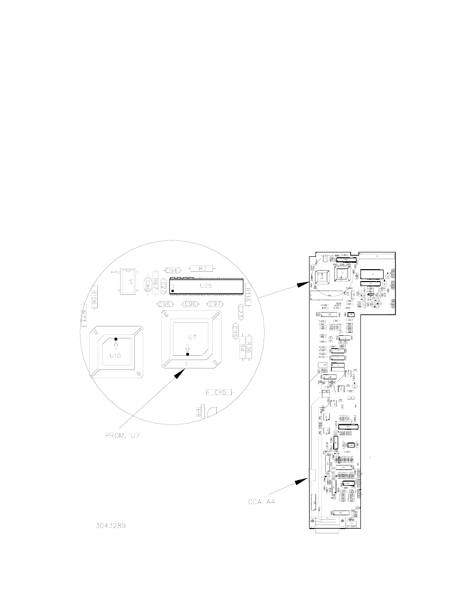
2.3 CIRCUIT CARD ASSEMBLY (CCA) A4 PROM U7 REPLACEMENT (SEE FIGURE 1)
1. Locate PROM U7 on A4 CCA near the front of the power supply. Note the orientation of the label of the device
installed in the PLCC socket. (see Figure 1).
CAUTION: FAILURE TO USE THE ESD WRIST STRAP MAY DAMAGE THE PROM!
2. Touch the IC tube to the chassis of the KLP, then open one end of the tube.
3. Insert the hooked end of the supplied PLCC extraction tool into one of the two tooling notches located at oppo-
site corners of the PLCC socket for U7. Applying firm, continuous pressure lift one corner of the PLCC free of
the socket, then lift the entire device free.
4. Examine the PLCC socket for damaged or bent contacts; if found, return unit to Kepco for repair.
5. Select the replacement device whose label bears the same serial number as that noted in PAR. 2.2, Step 2.
Orient the replacement device so that it is centered over the PLCC socket with the label oriented identically to
the original (see Step 1 above). Apply firm, even pressure to seat the new device fully within the socket.
6. Reinstall the cover by reversing the disassembly procedure (see PAR. 2.2, step 5).
7. Reinstall source power, load and programming cables and turn the unit on. Factory calibration is retained and
recalibration is not necessary.
FIGURE 1. CIRCUIT CARD ASSEMBLY A4 PROM U7 LOCATION