Table 2. rj45 to db9 adapter wire functions, Figure 1. rj45 to db9 adapter wiring – KEPCO Kit 219-0436, RS232 Cable Adapter Kit (RJ45 to DB9) User Manual
Page 2
KEPCO, INC. " 131-38 SANFORD AVENUE " FLUSHING, NY. 11355 U.S.A. " TEL (718) 461-7000
FAX (718) 767-1102 " email: [email protected]
2
228-1487 REV 4
051408
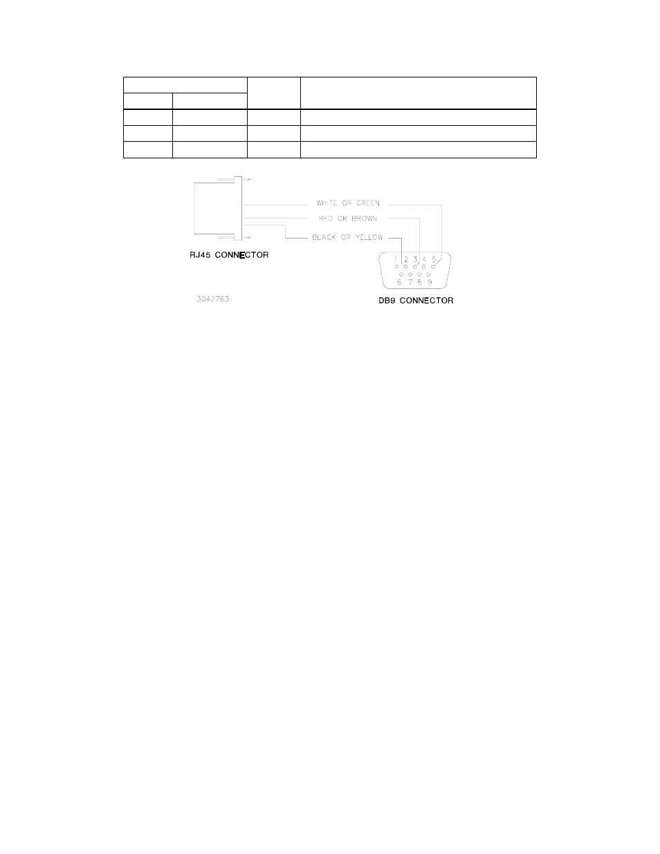
FIGURE 1. RJ45 TO DB9 ADAPTER WIRING
III.
ISOLATING RS 232 COMMUNICATION PROBLEMS
A Loop Back test can be run from the power supply front panel to aid in isolating RS 232 communication problems.
The unit is designed to pass the test only with the Loop Back test connector (see Table 1) installed.
1.
With the power supply in local mode, run the loop back test with the Loop Back Test connector NOT
installed and verify the test results in FAILED. If the test results in PASSED, the power supply is defective
and requires repair.
2.
Install the proper loop back test connector (either P/N 195-0110 for ABC and BHK-MG or P/N 195-0111 for
BOP) into RS 232 port and rerun the test. If the test results in PASSED, the power supply is operating prop-
erly. If the test results in FAILED, the unit requires repair.
3.
To check the connection between power supply RS 232 port and computer, disconnect the DB9 adapter
between the RJ45 patch cord and the computer. Install a short wire jumper (wire not supplied) between
pins 2 and 3 of the DB9 connector portion of the DB9 adapter. Plug the RJ45 patch cord into the DB9
adapter and rerun the test. If the test results in FAILED, RJ45 patch cord is defective. If the test results in
PASSED, remove jumper from DB9 adapter and reconnect DB 9 adapter between RJ45 patch cord and
computer.
4.
Verify the power supply is set to baud rate of 9600. Then, configure any RS-232 communication program
(such as Hyperterminal or Procom) to: baud rate to 9600, parity to off and bits per character to 8. Run the
loop back test while monitoring the RS 232 data. The communication program should show the following
data: KEPCO,ABC10-10,a12345,123 representing Manufacturer, Model number, Serial number and Firm-
ware version.
If data is not correct, unplug RJ45 patch cord from DB9 adapter, and insert loopback test connector into
DB9 adapter. Using the communications program send data to power supply and verify that data is
returned to computer. If data is not returned, computer is not functioning properly.
If data is returned to computer, remove loopback test connector from DB9 adapter and reconnect RJ45
patch cord to DB9 adapter. Use a null modem between DB9 adapter and the computer for proper RS 232
communication.
5.
When the data is correctly displayed, send *IDN? to the unit and use the communication program to verify
that the power supply responds with the same data as for step 5. If no data is shown, check the communi-
cation setup and verify the program is transmitting the line feed character.
TABLE 2. RJ45 TO DB9 ADAPTER WIRE FUNCTIONS
Wire
DB9 Pin
Purpose
BOP
ABC, BHK-MG
Green
White
5
Return for pins 2 and 3.
Brown
Red
3
Carries data from the controller to the Kepco power supply.
Yellow
Black
2
Carries data from the Kepco power supply to the controller.