Ii — installation/removal, Mounting on din rail, Removal – KEPCO KDN 24V Series Quick Start Guide User Manual
Page 2: Connections, Iii — operation
2
228-1673 REV 1
051310
KEPCO, INC. 131-38 SANFORD AVENUE FLUSHING, NY. 11355 U.S.A. TEL (718) 461-7000 FAX (718) 767-1102
http://www.kepcopower.com email: [email protected]
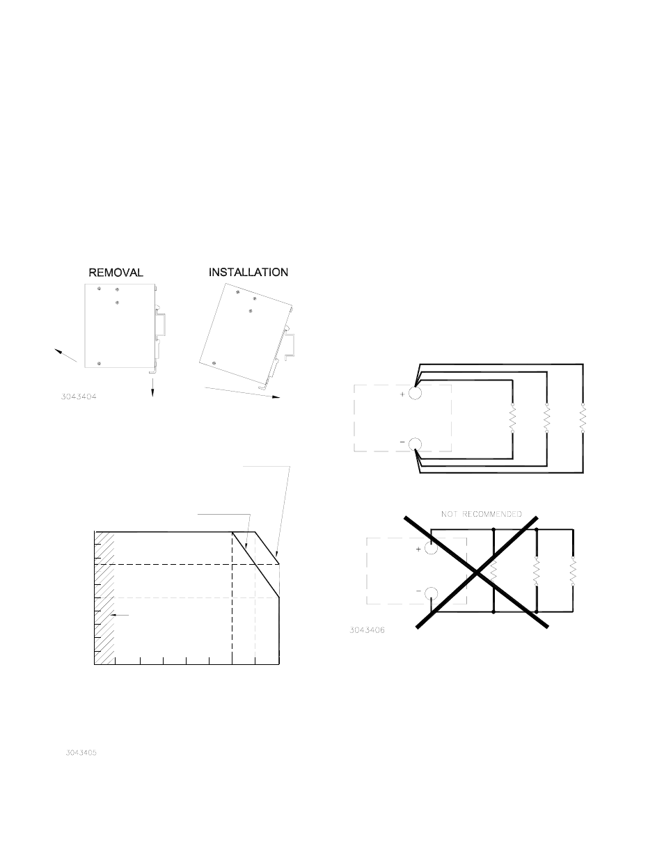
II — INSTALLATION/REMOVAL
MOUNTING ON DIN RAIL.
The KDN Series is
designed to mount on a 35mm DIN rail only as
shown in Figure 2 with ventilation holes at top and
bottom. Install by inserting one edge of mounting
bracket on DIN rail as shown, then press down to
snap onto DIN rail.
REMOVAL.
Remove by pulling hook down to
release mounting bracket from DIN rail, then swing
power supply away from DIN rail.
.
FIGURE 2. POWER SUPPLY MOUNTING
FIGURE 3. OUTPUT POWER VS. TEMPERATURE
CONNECTIONS.
Connect the load to the power
supply d-c output + + and – – terminals shown in
Figure 1. The AC input power is applied via the ter-
minal block. Make sure to connect the AC input Neu-
tral, Line and Ground wires to the respective
terminals of the terminal block (see Figure 1). Wire
strip length for both a-c and d-c connector is approx-
imately 1/4 inch (6 - 7mm). See Figure 4 for connect-
ing multiple loads. The Power Share terminal (KDN
24-20 only) is used only for parallel operation (see
KDN Series Operator Manual).
FIGURE 4. CONNECTING MULTIPLE LOADS
III — OPERATION
The Output Voltage Adjust trimmer (see Figure 1)
allows adjustment of output voltage from 23.5 to 28V
d-c. When output voltage is within adjustment range,
the green PWR OK LED is on. See Figure 3 for tem-
perature derating. The KDN 24-20 model may be
configured to operate in parallel; see Operator Man-
ual listed on page 1 for details.
Ambient Temperature (°C)
-10
0
10
20
30
40
50
60
70
10
20
30
40
50
60
75
90
100
O
ut
pu
t P
ow
er
R
at
in
g
(%
)
KDN 24-5 (115V A-C AND 230V A-C),
KDN 24-10 (115V A-C AND 230V A-C),
KDN 24-20 (230V A-C)
KDN 24-20 (115V A-C)
NOTE: Operation from -10°C to 0°C is as follows:
KDN 24-5: Yes, normal operation
KDN 24-10: No
KDN 24-20: Start up at -10°C, nominal line voltage only.
SEE NOTE.
A
B
CORRECT METHOD
POWER
SUPPLY
POWER
SUPPLY
LOAD
1
LOAD
2
LOAD
3
LOAD
1
LOAD
2
LOAD
3