Figure 4. jbw 100w mechanical outline diagram, Figure 5. input/output connections – KEPCO JBW 100W Series User Manual
Page 4
4
228-1552 REV 2
061510
KEPCO, INC. 131-38 SANFORD AVENUE FLUSHING, NY. 11355 U.S.A. TEL (718) 461-7000 FAX (718) 767-1102
http://www.kepcopower.com email: [email protected]
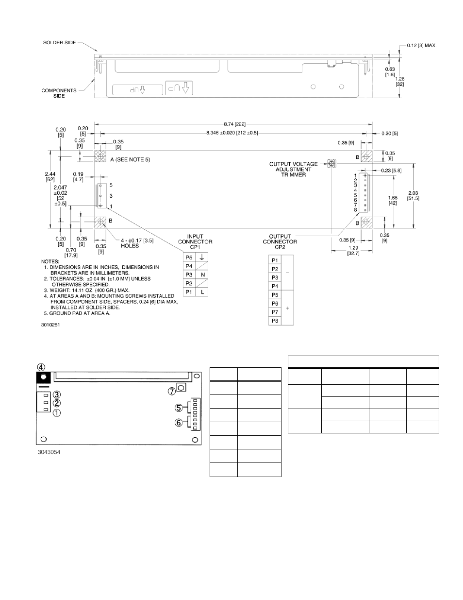
FIGURE 4. JBW 100W MECHANICAL OUTLINE DIAGRAM
FIGURE 5. INPUT/OUTPUT CONNECTIONS
Item
Function
1
Input L
2
Input N
3
Ground
4
Ground Pad
5
Output (-)
6
Output (+)
7
Vadj control
Mating Connectors(3)
Connector
Terminal Pin
Socket
Housing
MFR
Input
SVH-21T-P1.1
VHR-5N
JST(1)
T101
H101-05
LCE(2)
Output
SVH-21T-P1.1
VHR-8N
JST(1)
T101
H101-08
LCE(2)
(1) JST= Japan Solderless Terminal Mfg. Co.
(2) LCE= Long Chu Electronics Co.
(3) O
ptional cable kit (P/N 219-0495) includes
one input and one output cable (one meter
long) with mating connectors for Input and
Output connector, unterminated at other end.
INPUT
OUTPUT
See also other documents in the category KEPCO Power suppliers:
- ABC-DM SERIES (96 pages)
- ATE (all models) QUICK START GUIDE (8 pages)
- SN 488-D (94 pages)
- SN 488-D (14 pages)
- SN 488-D (16 pages)
- BHK-MG 200W (Full Rack) Series (152 pages)
- BHK-MG 40W (Half Rack) Series (148 pages)
- BIT 232 (72 pages)
- BIT 4882 (56 pages)
- BIT 4886 Quick Start Guide (4 pages)
- BIT 4886 Operator Manual (92 pages)
- BOP 100W, 200W, 400W (M, D) Quick Start Guide (8 pages)
- BOP 20-5ML Modification Sheet (1 page)
- BOP 20-10MC Modification Sheet (2 pages)
- BOP 36-6MC Modification Sheet (2 pages)
- BOP 100-2MC Modification Sheet (2 pages)
- BOP 50-4MC Modification Sheet (2 pages)
- BOP 100-2ML Modification Sheet (2 pages)
- BOP 72-3ML Modification Sheet (2 pages)
- BOP 50-4ML Modification Sheet (2 pages)
- BOP 36-6ML Modification Sheet (2 pages)
- BOP 20-10ML Modification Sheet (2 pages)
- BOP 72-6MC Modification Sheet (2 pages)
- BOP 36-12MC Modification Sheet (2 pages)
- BOP 20-20MC Modification Sheet (2 pages)
- BOP 100-4ML Modification Sheet (2 pages)
- BOP 72-6ML Modification Sheet (2 pages)
- BOP 50-8ML Modification Sheet (2 pages)
- BOP 36-12ML Modification Sheet (2 pages)
- BOP 20-20ML Modification Sheet (2 pages)
- BOP 1KW-MG Quick Start Guide (16 pages)
- BOP 1KW-MG Quick Reference Guide (2 pages)
- BOP 1KW-MG Operator Manual, Firmware Ver.4.12 and higher (196 pages)
- BOP 1KW-MG Operator Manual, Firmware Ver.4.08 to 4.11 (194 pages)
- BOP 1KW-MG Operator Manual, Firmware Ver.3.05 to 4.07 (194 pages)
- BOP 1KW-MG Operator Manual, Firmware Ver.2.48 to 3.04 (188 pages)
- BOP 1KW-MG Operator Manual, Firmware Ver.2.38 to 2.47 (188 pages)
- BOP 1KW-MG Operator Manual, Firmware Ver.2.01 to 2.37 (176 pages)
- BOP 1KW as Solar Device Tester Quick Start Guide (3 pages)
- BOP-GL 1KW Quick Start Guide (16 pages)
- BOP-GL 1KW Operator Manual Firmware Ver.3.05 and higher (168 pages)
- BOP-HV (48 pages)
- CA 26 (2 pages)
- CA 27 (2 pages)
- CA 29 (2 pages)