Figure 1. output power vs. temperature, Iii — installation, Mounting power supply – KEPCO JBW 150W Series User Manual
Page 3: Insulation, Ventilation, Connections, Iv — operation, Protection diode, Figure 2. mounting direction, Figure 3. ventilation and insulation requirements
KEPCO, INC. 131-38 SANFORD AVENUE FLUSHING, NY. 11355 U.S.A. TEL (718) 461-7000 FAX (718) 767-1102
http://www.kepcopower.com email: [email protected]
061510
228-1553 REV 2
3
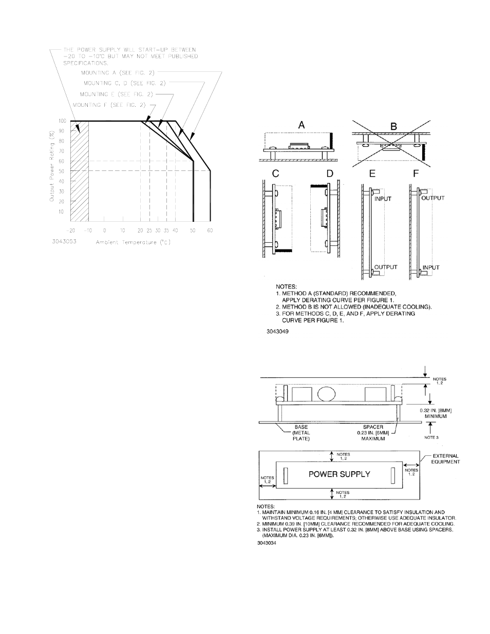
FIGURE 1. OUTPUT POWER VS. TEMPERATURE
III — INSTALLATION
MOUNTING POWER SUPPLY. Refer to Figures 2, 3
and 4. The unit may be mounted on one mounting surface.
Air temperature surrounding the power supply must not
exceed the ambient values given in the graph in Figure 1.
INSULATION. Install unit at least 0.3 inches (8mm)
away from base with 0.24 inch (6mm) diameter spacers
attached to the PC board. Keep at least 0.16 inches (4mm)
spacing around and above the unit to comply with insula-
tion and safety requirements. An insulator must be used if
the spacing is less than 0.16 inches (4mm) (see Figure 3).
VENTILATION.
It is recommended to keep at least 0.40
inches (10mm) clearance from adjacent equipment for
proper ventilation (see Figure 3).
CONNECTIONS.
Connect a load to the output of the
power supply by connecting pins 1 through 6 (+) of output
connector CON2 to the load (+) terminal, and pins 1
through 7 (–) of output connector CON2 to the load (–) ter-
minal. See Figure 4 for input/output connector and pin loca-
tions. When connecting the power supply to the load, keep
the wires as short as possible, and use twisted pairs (use
Wire Size AWG No. 22). Make sure there is only a single
ground point in the load circuit. Capacitors (100UF electro-
lytic and 0.1UF film) can be placed across the load to filter
out noise.The AC input power is applied via input connec-
tor CON1. Make sure to connect the AC input Neutral and
Line wires to pins 3 and 1, respectively, of CON1. See Fig-
ure 5 for mating connector information. A Cable Kit (P/N
219-0496) is available as an option from Kepco. The kit
includes one input cable, one output (–) cable and one out-
put (+) cable, each one meter long with the mating connec-
tors for Input and Output connectors at one end and
unterminated wires at the other end.
IV — OPERATION
PROTECTION DIODE: When a number of power sup-
plies are operating in series, the current rating is to be lim-
ited to the rating of the power supply with the lowest rating.
A diode (Vr>2 Vo, If>2Io, Vf<< low) must be connected to
the power supply output terminals to protect the unit from
reverse voltage.
FIGURE 2. MOUNTING DIRECTION
.
FIGURE 3. VENTILATION AND INSULATION
REQUIREMENTS
Σ