Figure 2. rear connector pin assignments – KEPCO HSF 350W Series User Manual
Page 3
040803
228-1367 REV 6
3
KEPCO, INC. " 131-38 SANFORD AVENUE " FLUSHING, NY. 11352 U.S.A. " TEL (718) 461-7000 " FAX (718) 767-1102
http://www.kepcopower.com " email: [email protected]
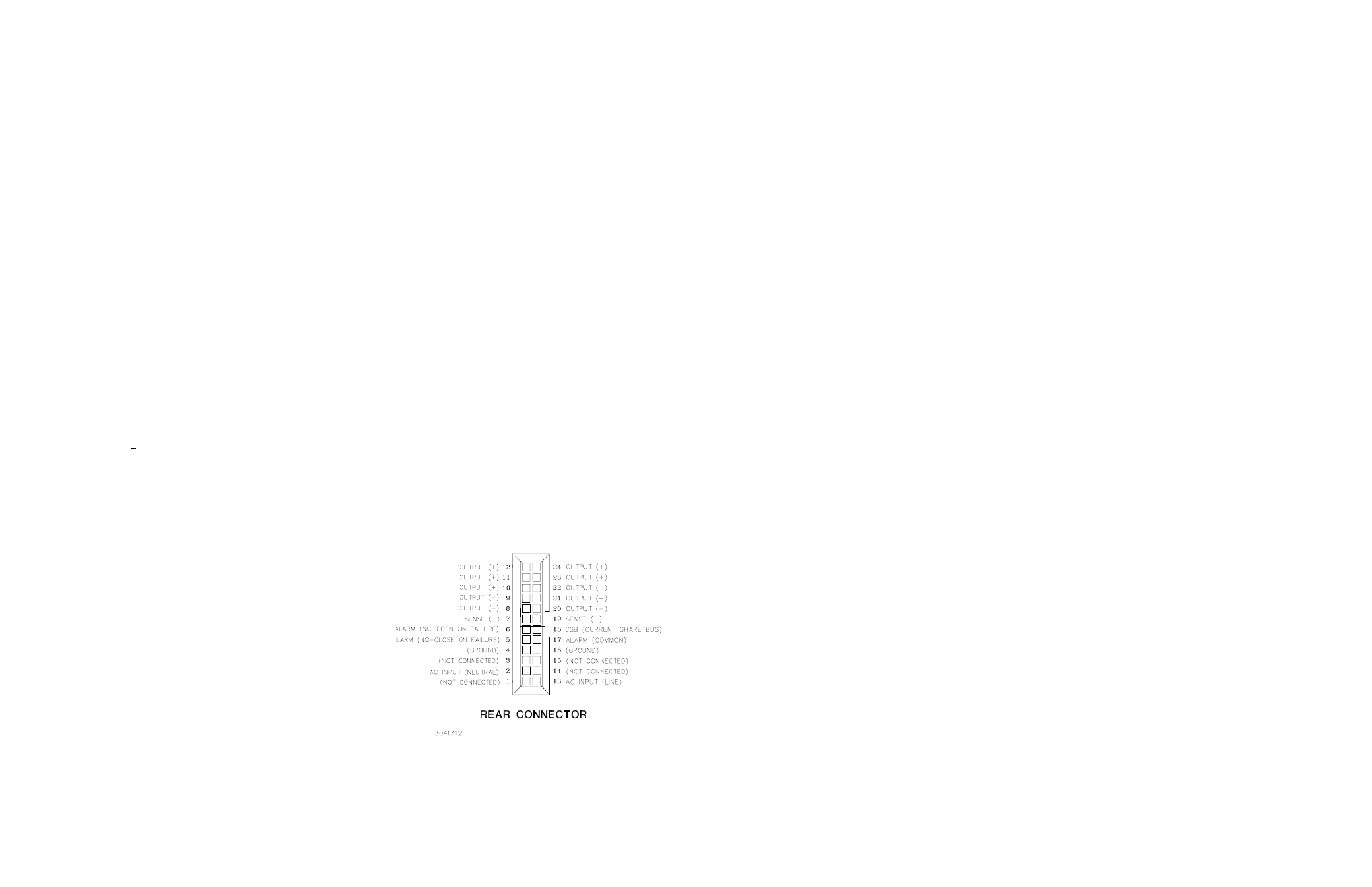
I/O CONNECTOR:
The 24-pin I/O connector (Figure 2) is designed to mate with the corresponding connector in the Series RA 19-(X)B
Rack Adapter.
# (+) SENSE, (–) SENSE:
These lines are provided to compensate for voltage drops in the load connecting wires. The Sense lines
must be connected to their respective (+) and (–) output terminals, either at the load or at the rack adapter (see Rack Adapter Manual).
The connection ensures the most accurate error tracking. Error compensation in the connecting wires is up to 0.25 Volts per lead for all
models.
NOTE:
The Sense lines must be connected for the HSF Power supply to work properly!
# OUTPUT (+), OUTPUT (–):
HSF power supply d-c output.
# CURRENT SHARE BUS (CSB):
Connecting the CSB lines of HSF power supplies operating in a parallel configuration causes out-
put current to be shared equally. (See Rack Adapter Manual for additional information on parallel configurations.). For current sharing to
work properly the outputs of all paralleled units must be within 250 mV (max) of each other. For master/slave operation to work properly
each unit should be adjusted to 40 mV (optimum) less than the next paralleled unit (unit 1 is adjusted to V
OUT
, unit 2 to V
OUT
– 40mV,
and unit 3 to V
OUT
– 80mV, etc. If the master fails, the unit 2 will become the new master). The 40 mV difference can be reduced to a
minimum of 25 mV as needed to parallel many units and still keep all units within 250 mV of each other. Adjust the outputs using Vadj
trimmer on front panel.
•
Optimum difference among output voltages of paralleled units: 40mV
•
Maximum difference among output voltages of paralleled units: 250 mV
•
Minimum difference among output voltages of paralleled units: 25 mV
# ALARM:
The Alarm NC (normally closed) - Open on Failure and Alarm NO (normally open) - Close on Failure lines are relay contacts
referenced to Alarm Common. If the unit fails, the path between Alarm NC - Open on Failure and Alarm Common opens, the path
between Alarm NO - Close on Fail and Alarm Common is a short circuit. Figure 3 illustrates typical Close on Fail and Open on Fail cir-
cuits to give a failure indication if any one of a number of power supplies fail.
# INPUT POWER:
Line (either a-c or d-c source power), Neutral and Ground (chassis)
EMI:
Designed to meet FCC (100-120V a-c) Class A
(220-240V a-c).
VIBRATION:
(non-operating, one hour on each one of the three axes):
5-10 Hz, 10 mm amplitude.
10-55 Hz, 2g acceleration.
SHOCK:
(non-operating, one-half sinusoidal pulse, three shocks to each axis):
Acceleration: 20g
Duration: 11ms +5ms
OPERATING TEMPERATURE:
See Figure 4.
STORAGE TEMPERATURE:
-30
o
C to +75
o
C.
OPERATING AND STORAGE RELATIVE HUMIDITY:
up to 95% (wet
bulb temp. <35
o
C non-condensing).
FUSE:
Quick acting 10A, 250V; (1-1/4 x 1/4 in.), Little, P/N 314010;
Kepco P/N 541-0125
DIMENSIONS:
See Figure 5.
WARRANTY:
5 years.
NOTE: 3.3V AND 5V UNITS USE TWO CONNECTORS.
•
LH CONNECTOR IS SHOWN ABOVE.
•
RH CONNECTOR PINS 8 THRU 12 AND 20 THRU 24 ARE
AS SHOWN ABOVE; PINS 13 THRU 19 AND 1 THRU 7 ARE
NOT USED. .
FIGURE 2. REAR CONNECTOR PIN
ASSIGNMENTS