Iii — specifications – KEPCO HSF 350W Series User Manual
Page 2
2
228-1367 REV 6
040803
KEPCO, INC. " 131-38 SANFORD AVENUE " FLUSHING, NY. 11352 U.S.A. " TEL (718) 461-7000 " FAX (718) 767-1102
http://www.kepcopower.com " email: [email protected]
ALARM CIRCUIT.
The HSF includes an isolated internal relay offering normally closed and normally open contacts referenced to an
isolated common. These contacts may be used to configure “close on failure” or “open on failure” alarm circuits. (Refer to the Series
RA 19-(X)B Manual for alarm configurations for multiple HSF power supplies.)
KEYING.
Keying of the HSF is established at the factory. The output voltage determines which keyway is open (see Figure 5). When the
corresponding rack adapter key (pin) is installed by the user, only a power supply of the correct voltage can be inserted in the rack adapter
slot.
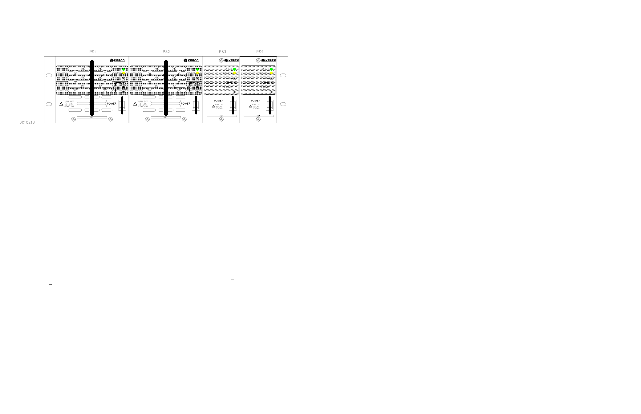
FIGURE 1. RA 19-4B RACK ADAPTER WITH TWO 1/3 RACK AND TWO 1/6 RACK HSF POWER SUPPLIES INSTALLED.
III — SPECIFICATIONS
The following specifications apply to all HSF 350 Watt Series models (also refer to Table 1). Other models are also available; consult your
Kepco representative for their specifications.
INPUT:
Voltage: 100/120/220/240V a-c nominal; Range 95-264V a-c; 110-370V d-c. (polarity insensitive)
Frequency: Nominal 50-60 Hz; Range 47-440Hz (at 440Hz leakage current exceeds UL/VDE safety spec.limit).
Current (nominal output at rated load):
All Models except 3.3V:
@120V a-c rms: 4.0A a-c typ., 5.6A a-c max;
@240V a-c rms: 2.0A a-c typ., 2.8A a-c max.
3.3V Models:
@120V a-c rms: 3.0A a-c typ., 4.0A a-c max;
@240V a-c rms: 1.5A a-c typ., 2.0A a-c max.
Initial Turn-on Surge: (one-half of first input cycle): @120V a-c rms, 20A max; @240V a-c rms, 40A max.
When the a-c input power is removed, the inrush current limit circuit requires 30 seconds recovery time before the
a-c input power is reconnected.
Brownout Voltage: 80V a-c, 110V d-c.
Switching Frequency: Main converter (forward):150KHz typical; PFC converter: 120KHz typical, nominal load.
Power Factor: 0.99 typ. (per EN 61000-3-2)
Efficiency: max load, nominal output:
All Models except 3.3V: 72% typ.
3.3V Models
65% typ.
STABILIZATION:
Source Effect: Range 95-132V a-c or 190-264V a-c, 0.05% typ.; 0.1% max.
Load Effect: Range 0%-100% load, 0.2% typ.; 0.3% max.
Temperature Effect: Range -10
o
to 40
o
C, 0.5% typ.; 1.0% max.
Combined Effect: 0.7% typ.; 1.5% max. (includes source, load, and temperature effects).
Time Effect: 0.2% typ.; 0.5% max. (1/2 hr-8-1/2 hr, max load at 25
o
C).
RECOVERY CHARACTERISTICS:
A step load change from 50% to 100% produces less than +1% output excursion. Recovery
occurs to within +1% of the original setting in <1 ms (load change t
r
or t
f
equal to or greater than 10
µ
sec).
START-UP TIME:
900 ms. maximum, 500 ms. typ.
HOLDUP TIME:
30 ms. typ. (120V a-c), 20 ms. min. (120V a-c).
DIELECTRIC STRENGTH:
Between input and output: 2.5KV a-c for one minute.
Between input and output with Y-capacitor removed: 2.5KV a-c for one minute.
Between input and case (ground): 2.5KV a-c for one minute.
INSULATION RESISTANCE:
Between input and ground, output and ground, input and output;
100 Megohms min. (500V d-c).
LEAKAGE CURRENT
UL method, 120V a-c: 1.0 mA maximum.
VDE method, 240V a-c: 2.0 mA maximum.
BELLCORE REQUIREMENTS:
NEBS GR-63-CORE
SAFETY:
UL1950 3rd. Ed., CSA 22.2 No. M950. Units Designed to meet EN60950 and are CE marked per the Low Voltage Directive
(LVD), 73/23/EEC and 93/68/EEC. [The standards do not apply with DC input operation]
B3010218